• Please review our updated Terms and Rules here

Cbm 2001 Pet strange boot

So, I am assuming that it was Nivag’s ROM code that did appear to work (it has an “e=xxxx” as part of the display and mine doesn’t.

Nivag, do you want to run with this fault for a bit to save us both going in different directions?

Dave
 
CONFIGURATION A:


PETTESTER UD9 POSTED BY NIVAG


ALL ORIGINAL ROMS INSERTED ON BOARD


PIA AND VIA ON BOARD
 
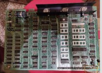
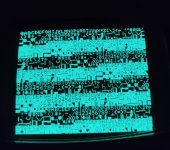
@Dave_C78 Remove ALL ROMS except the Character Generator ROM, place them safely outside the machine. Insert the ROM with the UD9.bin image into UD9. Remove BOTH PIAs and the VIA and put them safely outside the machine.

Take a Photo and post it of the board... showing the installed components and the resulting screen.

Report Back with the evidence above.

We can call that Configuration BRAVO
 
Last edited:
CONFIGURATION A:

PETTESTER UD9 POSTED BY NIVAG

ALL ORIGINAL ROMS INSERTED ON BOARD

PIA AND VIA ON BOARD

Which one of Nivag's testers? What about the configuration without the PIAs (ie, both) and the VIA? You need to be precise and detailed. I guarantee you won't remember in two days time after some more chip swapping and I certainly won't!

Alan
 
@Dave_C78 Remove ALL ROMS except the Character Generator ROM, place them safely outside the machine. Insert the ROM with the UD9.bin image into UD9. Remove BOTH PIAs and the VIA and put them safely outside the machine.

Take a Photo and post it of the board... showing the installed components and the resulting screen.

Report Back with the evidence above.

We can call that Configuration BRAVO
Ok this evening i ll try this configuration...with screen s' picture!
 
@Dave_C78 Remove ALL ROMS except the Character Generator ROM, place them safely outside the machine. Insert the ROM with the UD9.bin image into UD9. Remove BOTH PIAs and the VIA and put them safely outside the machine.

Take a Photo and post it of the board... showing the installed components and the resulting screen.

Report Back with the evidence above.

We can call that Configuration BRAVO
Ok this is BRAVO configuration.
 

Attachments

  • Schermata 2022-05-13 alle 19.55.41.jpg
    Schermata 2022-05-13 alle 19.55.41.jpg
    155.8 KB · Views: 8
  • Schermata 2022-05-13 alle 19.55.55.jpg
    Schermata 2022-05-13 alle 19.55.55.jpg
    135.5 KB · Views: 9
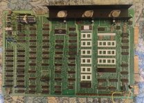
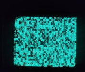
This is CHARLIE configuration.
 

Attachments

  • Schermata 2022-05-13 alle 22.41.40.jpg
    Schermata 2022-05-13 alle 22.41.40.jpg
    145.2 KB · Views: 7
  • Schermata 2022-05-13 alle 22.41.56.jpg
    Schermata 2022-05-13 alle 22.41.56.jpg
    120.3 KB · Views: 6
The 'simple' test for a bad socket is that if you put one EPROM into it (configuration BRAVO) and this consistently works whereas putting another EPROM into the socket (configuration CHARLIE) and this consistently fails - it is unlikely to be the socket.

For it to be the socket, I would expect configuration BRAVO to also fail some of the time.

Can you remind me what EPROM configuration CHARLIE exactly is (i.e. manufacturer and the exact part number). Some EPROM manufacturers produced EPROMS with the same type number - but they were incompatible with each other!

Dave
Good morning Dave, today sun is shining in Italy... good sign for Pet ?? ;)
Charlie is burned on TMS2732F JL-45
 
Just toast and coffee.

Yep, the sun is shining in Worcester as well!

I can’t find a datasheet online for the Texas ‘F’ part you have...

The -45 means 450 ns access time.

Out of interest, what part number is the EPROM used in configuration BRAVO.

In the meantime, I’ll see if I can find the full Texas databook. I have one at work...

Dave
 
Reburn the magic_rom.bin into a new device and replace UD9

We can call this Configuration DELTA

With DELTA turn the machine on, take the photos and with a logic probe check the signals at the CPU (at C4)... ideally post details for every pin but at least pins 4,6,7,9,34 and 40
 
Simples...

A TMS2532 and a TMS2732 have different pinouts. The two are INCOMPATIBLE with each other.

A 2532 EPROM has A11 on pin 18.
A 2732 EPROM has A11 on pin 21.

UD9 has A11 on pin 18. Hence, only a 2532 will work. QED!

A 2732 ‘can’ be made to work, but only under special circumstances... Although I don’t believe this to be the case with UD9. The restart vector will have A11=HIGH on the socket of UD9. This will mean that the /E pin of a 2732 will be HIGH = disabled.

I believe you can use a 2732 in the EDIT ROM socket (using the low 2K half of the 4K address range) provided the code itself is written into the upper 2K of the 4K EPROM - if all this makes sense?

To use all 4K of a 2732 will require an adapter to ‘switch’ the A11 pin (and other(s)).

Dave
 
Last edited:
Back
Top