• Please review our updated Terms and Rules here

Need help with IBM 5151 monitor troubleshooting

"My Oscope works but its very dim, I can see the waveforms but I need to find the subbrightness and dial it up as the pulses are faint, but I can still see them."

You're treading on thin ice. Fixing old oscilloscopes can be another hobby that will suck in the unwary.

;-)
trust me i already got rid of two others. a 1957 devry tube oscope and a 1985 Hp logic analyzer.


I was just thinking
is there a chance one of the pins on the video cable might have a break? Maybe I should have checked the cable?
 
I was just thinking
is there a chance one of the pins on the video cable might have a break? Maybe I should have checked the cable?
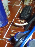
Obviously, you must be writing of a cable that runs from the main board up to the yoke board, a cable carrying the contrast-adjusted video signal.

My earlier "... measure the resistance between pin 8 of IC201, and the base of TR19." will inform you of the situation. If that indicates a circuit 'break', there are various possibilities as to the cause. Even just re-seating the connectors on the subject cable may do something. But if the measurement is as expected, there is no point.
 
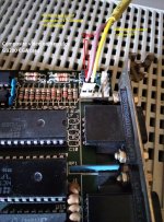
Well the troubleshooting instructions were spot on. I was just measuring resistance when I could not find the signal transfer from the neckboard to the main pcb.
I was testing each wire and found one not connected.
Upon closer inspection it had some strange brown gross stuff on it and the wires were corroded through on the V1 connection point.
I dont know what this leaky stuff Is I thought adhesion of some king but it was corrosing the copper. Seems they screwed up when assembling this pcb as only 3 strands were ever connected!

I will work on reconnecting it. Should be easy.

IMG_20220929_102830.jpg

Edit: on closer inpection this is singe stranded wire. Wow thats delicate. I saw 3 green spots where it corroded I thought those were the strands, but no. single strand.
 
Last edited:
Ok So I cleaned up the wires and the solder points and reconnected them. I have video now.

I have learned something else. Both my full length Hercules graphics cards have bad video ram. Both show artifact characters in on screen but differently. And at least one of them is giving the wrong text when I am navigating directories.That will need to be addressed.

I also found in my box a 3rd very small hercules card I got in a pickup I never tested. IT only makes the system beep a couple codes with no graphics so I dont know what is wrong with that card.
IMG_20220929_120704.jpgIMG_20220929_120713.jpg


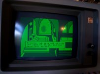
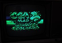
Setting the screen geometry with the IBM MGA card is rough since I cant load any good fullscreen programs so I used the glitchy hercules card to load Kings Quest II. I can say the internal geometry adjustments for the 5151 are incredibly lacking. This is the best image I can get, I can stretch it no further. I can use the centering rings to center it but there is so much wasted border space. Thats dissapointing. Here is the image: You can see some of the bad graphics artifacting randomly. But anyway Monitor is fixed!

Thank you everyone and thank you especially @modem7
IMG_20220929_120118.jpg
 
Yeah GB200 REVB. Most of the chips are dated 84 so I assumed they only made MDA cards at the time. Thanks for clearing that up. Strange to see a CGA card with no composite though, Are any of these pin headers connected to a composite CGA line? I can solder on the connector.
 
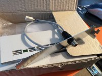
According to the manual it has composite output via an adapter. Not sure if it plugs into the pin headers or DE9.
 
Yeah it's not the full manual. I happen to have a random DE9 to RCA adapter, no idea what it's from. It has the ground connected to pin 1 and the signal connected to pin 7.
 
It appears to be photos from an eBay add for that manual, from some crazy person that wants $45 for it.

D760E5B5-F615-4A5E-8D02-4EB0953222C4.jpeg
 
I have that same de9 to rca adapter Plasma and have never found a use for it. Something tells me this is not it. I have never seen composite CGa come out the DE9 port.
 
The manual mentions plugging in the 5155 composite cable into a header P1, so I'd imagine the adapter included was also plugged in there.

I’ve got an adapter like this:
50D0F8CF-8DD2-49CB-A948-76A91E0C1A79.jpeg

Not sure exactly what it came with, but I’m assuming it’s something like this color card.
 
Now thst the 5151 is working I would like to try fixing the IBM MGA graphics card. Is there a troubleahooting guide to repair this card?
 
Ok I figured out the Hercules GB200 CGA card composite out. I found the ground pin and that was that
IMG_20220930_121630.jpg


I can the 8088mph demo via cga composite out to my Zenith bench monitor:
IMG_20220930_121551.jpg

Problem solved.


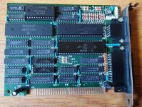
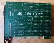
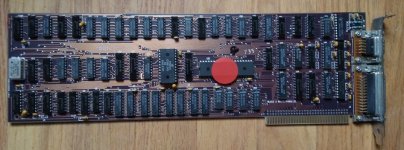
But seriously if anyone has any info on repairing a dead IBM BLACK X WHITE/PARALLEL card which was what came with this 5151 monitor I repaired . Please let me know. ITs a sea of soldered on TTL Logic and I dont know where to begin. It was shorting out the psu so I replaced the tantalums. Now it doesnt short but I get system beeps with no video (i add red stickers to everything needing repair fyi)

IMG_20220930_121648.jpg
 
But seriously if anyone has any info on repairing a dead IBM BLACK X WHITE/PARALLEL card which was what came with this 5151 monitor I repaired . Please let me know. ITs a sea of soldered on TTL Logic and I dont know where to begin. It was shorting out the psu so I replaced the tantalums. Now it doesnt short but I get system beeps with no video (i add red stickers to everything needing repair fyi)
There is only so much that you do with a logic probe or oscilloscope. Beyond a certain point, a logic analyser is required, but you should not be rushing out to get one of these. A logic probe may be enough to fix the probem.

1. As always, do a thorough visual inspection if you haven't already.

2. The card has an oscillator unit (the 'can'). Via logic probe or oscilloscope, preferably the latter, verify that the oscillator unit is producing a clock (ideally verifying decent waveform and correct frequency).

3. So the 'beeps' that you refer to is the typical '1 long beep then 2 short beeps' produced by the POST. Correct?

Yes one long and two short beeps in duration.


I will have to check the Oscilator later when I have time to get it back on the bench,.
 
Back
Top