Small update-
Got the original PS board reassembled with new 7805 regulator/heat-sink and otherwise original components.
And of course, pictures-
View attachment 1245264View attachment 1245265
The dented, sleeveless capacitor, the chipped tantalum along with its intact mate, the two resistors, and the pair of diodes.
All original parts extracted from the brick! Hopefully they play nice with the 'new' (dated '88) 7805 regulator.
While I currently lack a meter capable of testing the 4700uF 16V electrolytic, both tantalums are unshorted and read very close to their stated values, as do both resistors, while the diodes are unshorted and read nearly the same values on my meter.
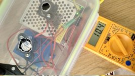
So! Rig up the lot of it with a line-cord, the original transformer, and at least 8 gator-clip leads, to get this-
View attachment 1245266
Then we brace ourselves and gingerly place the plug in the wall-socket to receive...
View attachment 1245267
A lit bulb and a stable 5 volts! How about that.
Now, I need to buy more solder because I used the last I had on-hand to reassemble that.
After all, I have a saver-circuit and an improved-version power-supply to build!
Reforming the original black plastic casing of the brick (it's a bit warped/ballooned from the chemicals the epoxy out-gassed) and gluing its ends back on will be a whole 'nother adventure.
But I've got JBweld Plastic Bonder, CA-glue with baking-soda, and a heat-gun, so it's mostly a matter of making wooden forms from lumber scraps to help massage it back into proper square shape, or close enough.
Plus I've got a couple threads about salvaging DIN plugs and alternate uses for dead IDE/floppy cables to write up/take pictures for.
Always lots to do when one has many hobbies. And this is only one aspect of my life amongst many. Such is life.
Have fun out there on your own projects and stay safe!
To be continued when I have time.


")