• Please review our updated Terms and Rules here

Amstrad PC 2286

Thanks for bringing this to my attention! I'll see if they reply to inquiry.

But first, today a few of the major ic's arrived that I ordered in the beginning of may.
Including the STK7458. I will see if changing that makes any difference!
 
Okay,

pull out the old one and install the new. It's been a while since my soldering iron was hot,
but nice clean pull, I did not even bend any legs of the big IC. Some new heat sink paste
before installation, new solder for the new IC and done. Spot on soldering work (this time).

But. You guessed it, no change in the psu operation. I measured voltage of every leg of this IC
(will not post it here) - there were no change in the voltages. At least, I'm pretty sure now that issue
lies elsewhere and not in this IC.

I think I should pull the big diode D616 next. It is next suspect, because its resistance between
legs is rather small. I just don't have it at hand yet, it's still on its way from UK to Finland.

I do have the -5V and -12V regulators though. Maybe I'll use the waiting time to replace these.
Then they'd be checked as well.

I just hope I'm not chasing ghosts here. Do I need more load to turn on the PSU ? I have
the floppy and the HD. I haven't plugged the psu to the motherboard. I wanted to have nice
steady voltages before attempting that.
 

Attachments

  • 1.jpg
    1.jpg
    51.8 KB · Views: 10
  • 2.jpg
    2.jpg
    27.6 KB · Views: 9
  • 3.jpg
    3.jpg
    63.8 KB · Views: 11
  • 4.jpg
    4.jpg
    52.3 KB · Views: 8
  • 5.jpg
    5.jpg
    45.6 KB · Views: 8
  • 6.jpg
    6.jpg
    59 KB · Views: 9
I have changed the -5V and -12V regulators now, but these did not help me out either.
I still have several other IC's that I can try to replace. I have pulled the bid diode D616 out
of the motherboard. I'm waiting for the spare to arrive in the mail, but the pulled diode
actually looks good now that it is out of the pcb. So it looks like problem probably still lies elsewhere.
 
Well, that is a good question!

No, I'm not and I have to rule that out. I will try those out with some other AT psu that I'm sure is in working condition and/or
use modern hard drive as load that I know works.

At the moment, the amstrad psu is lacking diode D616. I'm still waiting (for 3 weeks now) a replacement that I ordered from UK.
I'm assuming Brexit caused significant delay on shipping, unfortunately. I'll probably put that original diode back to the psu
and keep on working at this, because it looks good now that it's been pulled out of the pcb.

I also pulled one big cap out of the way from in front of that diode to gain access. there seemed to be some moisture
under the cap, but I'm not sure if it is the flux I used myself while pulling it out. It does not really look like the cap leaked,
but I'm not sure. One way would be to replace all electrolytic caps, but there are quite some and that would start to mount costs too.
The bigger ones aren't that cheap.
 
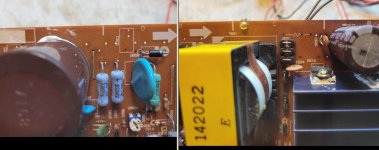
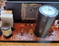
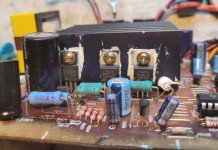
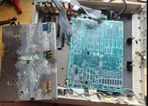
No new diode in my mailbox when I got home from work. That does it. I put the old diode back to
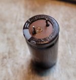
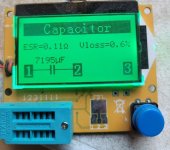
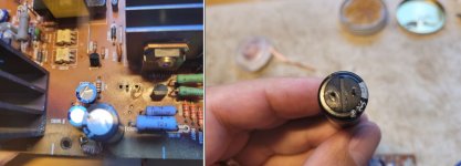
the pcb to continue checking. Also, cap C628 went back to the pcb. Although it looked a bit nasty at the
bottom, its ESR value seems reasonably ok if I compare it to tables found on-line.

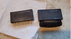
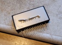
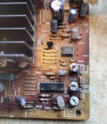
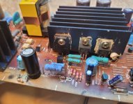
Now, I got new replacements for IC605 and IC603. Pulled the old ones out and installed IC sockets. These
too unfortunately changed nothing.

When power is turned on, the 5V fan spins for say, one second and then stops. Hard drive(s) do not do anything.
I'm using modern hard drive to test that works on ATX psu. By the way, I did also try now the old 40Mb hard drive
with the ATX psu and at least it does start spinning! So that at least is not completely dead, though this does not confirm
that it actually will work, yet. Floppy drive does not react at all either with the ATX psu, so I tried a bit more modern
floppy. Also that had no effect. I had assumed that at least the LED flashes at least once, but nothing. I therefore will always
use the HD as load when testing this. The new one, I don't want to stress out the good old hard drive unnecessarily.

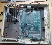
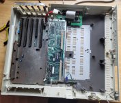
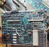
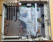
Furthermore, I wanted to see if plugging in the amstrad 2286 motherboard changes things with the psu. If that was
required to be on for the psu to turn on. That too had no effect.

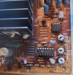
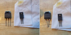
I think I may run out of ideas soon. I still have a couple of 2sc1815 transistors that I could use to replace Q616 and Q606.
Soon after that I should try to figure out what are the next bunch of components that I should order in hope to bring
this unit back to life.

edit:
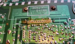
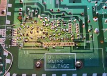
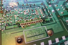
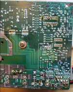
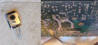
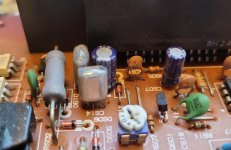
Oh yeah, there are some strange things at the pcb. Like R601 and C606 that are missing completely.
But there is nothing suggesting there ever was anything there after the factory, no broken legs or loose pieces
inside the psu box. Maybe this psu is updated version from Amstrad 2086 psu and not required in this computer version.
Just a bit odd that these markings are here, but no components are installed on them.
 

Attachments

  • 7.jpg
    7.jpg
    65.2 KB · Views: 7
  • 6.jpg
    6.jpg
    46.2 KB · Views: 5
  • 5.jpg
    5.jpg
    85.1 KB · Views: 6
  • 4.jpg
    4.jpg
    57.3 KB · Views: 8
  • 3.jpg
    3.jpg
    61.1 KB · Views: 10
  • 2.jpg
    2.jpg
    22.7 KB · Views: 9
  • 1.jpg
    1.jpg
    45.2 KB · Views: 10
I would not suggest reusing those leaking capacitors, they are not good and the leaking electrolyte will damage the PCB. The electrolyte is also conductive, so if it spreads between multiple metal points on the board, it will cause a variable short.

You need to replace all of the capacitors with known good ones before you do any more troubleshooting, else you'll be chasing ghosts.

As for the one cap you did test showing 7195 uF, is that a 6800 uF capacitor? If it isn't, then its VERY bad.
 
Thanks GiGaBiTe for our input!

Yes, you're correct, that is 6800 uF / 16V cap. I wasn't completely sure if it had leaked, but you're probably right.
My ESR meter is very low end, but perhaps it is really reading that value correct.

I noticed that I also had one more hot going component that I had not changed - the Q614 or B1135 transistor.
I had ordered replacement for that as well, but unfortunately I was sloppy when ordering. Original was
TO220 package and what I got was TO3P package. Replacement is 2SB827 transistor that should otherwise be
correct replacement for it.

I decided to try if I can put it there. Bent the legs a bit closer together, put a little heat conducting paste there and yeah - it did
go to the pcb without any issue.

I first had removed C625 (3300uF / 35V) electrolytic cap to gain access to replace that Q614. Ohh... and behold that!
When I was not sure about C628 had leaked, I am pretty convinced that this C625 at least is very bad boy! The positive
leg has very convincing evidence of leakage (to me at least).

That C625 is also directly connected to Q614 that was my last hot component replacement. Even if that hot transistor
was ok, perhaps this leaked cap is making it misbehave. I don't have any of these bigger caps at my stock, but leaked
one doesn't go back to the pcb. It seems, I have do have to list all of the bigger electrolytic caps and make order before
I can continue troubleshooting.

The last image is ESR meter values of that leaked cap.
 

Attachments

  • 13.jpg
    13.jpg
    47.1 KB · Views: 8
  • 12.jpg
    12.jpg
    64.9 KB · Views: 6
  • 11.jpg
    11.jpg
    45.1 KB · Views: 6
  • 10.jpg
    10.jpg
    83.5 KB · Views: 4
  • 9.jpg
    9.jpg
    63.6 KB · Views: 4
  • 8.jpg
    8.jpg
    51.9 KB · Views: 6
Yes, you're correct, that is 6800 uF / 16V cap. I wasn't completely sure if it had leaked, but you're probably right.
My ESR meter is very low end, but perhaps it is really reading that value correct.

Those cheap chineseium meters are fine for hobbyist use, you just have to know their limitations. When testing capacitors, you need to take note of the capacitance and ESR, not just the ESR. If the capacitance value it gives you is more than +/- 20% off, the cap is bad. Quality capacitors will generally have a tolerance better than 20% though, usually around 5-10%, even if they say 20%. If you test say a 1000 uF capacitor and it registers like 3841 uF, it doesn't mean the capacitor is over-achieving, it means that it has an internal failure and has turned into a resistor. This confuses the tester because it will drain the charge the tester puts in too fast and skew the reading. Likewise, if it shows up as a diode or a really low capacitance, it usually means there's a short or the seal failed and the electrolyte dried out.

Also be aware of false readings. I have a variation of that tester that cannot test 47 uF capacitors of any voltage rating due to a bug in the code on the device. I figured this out when I ordered a big batch of 47 uF caps and they were all testing bad. I had to use a different meter to test them.

And finally, MAKE SURE the capacitor is fully discharged. These cheap meters have no input protection, and usually just wire directly into pins on a microcontroller. Anything over a volt or two and you're probably going to fry it. I've gone through several meters because of this.

The last image is ESR meter values of that leaked cap.

That ESR value is too high, I would expect 0.4 ohms or less. The larger a capacitor is in physical size, generally the lower the ESR is unless it's a specialized capacitor. High voltage and non-polar electrolytics can have higher ESR than lower voltage ones.
 
Thanks again for instructions and warnings.

I decided to order major electrolytic caps:
C625 - 3300 uF/35V
C627 and C628 - 6800uF/16V
C629 and C640 - 1000uF/16V
C630 - 330uF/35V
C623 - 330uF/63V
I have these at my stock: C635 and C636 - 100uF/50V. There are number of smaller caps at the psu pcb, but I just now ordered these.
I also ordered 60x25mm 12V fan for the psu. I have to correct myself, I had been referring to this fan as 5V fan, but in fact it was 12V.
The original fan is probably fine, but as someone suggested earlier here, it can be noisy. Perhaps replacing it make the computer
more comfortable to use. I spent about 28 € for these, shipping included. They have already shipped, but I don't expect to receive them
before next monday. Had I ordered these from china, I might have saved more than half the cost. But it can literally take several months nowadays
for items to arrive here and I'm not willing to wait that long.

While waiting for the caps, I thought it is a good time to check the motherboard. It looks like the 286 motherboard and the extension
board (why in the hell these are divided in two...?) have both survived pretty well compared to the psu. I could not see much corrosion
there luckily. Maybe there is hope for this thing yet!

Dirty they were, especially the casing. leftovers of dead bugs and corrosion on the casing. I gave the case and the metal protection plates a good wash.
Not perfect, but clean enough for me. Much nicer anyway and comfortable to touch compared to earlier pile of filth.
 

Attachments

  • 8.jpg
    8.jpg
    133.4 KB · Views: 13
  • 7.jpg
    7.jpg
    125.6 KB · Views: 12
  • 6.jpg
    6.jpg
    62.6 KB · Views: 10
  • 5.jpg
    5.jpg
    47.1 KB · Views: 11
  • 4.jpg
    4.jpg
    64.9 KB · Views: 12
  • 3.jpg
    3.jpg
    147.4 KB · Views: 14
  • 2.jpg
    2.jpg
    148 KB · Views: 13
  • 1.jpg
    1.jpg
    127.7 KB · Views: 12
Mailman surprised me today as shipment of caps arrived! much earlier what I supposed.
Replaced all the newly arrived caps. Still no change in the unit.

That's a bit of a bummer. All major IC's and bigger caps are replaced now. Well... almost all caps,
there's one really big that I did not yet change, but I don't think this has to do with the problem.
It's got >200 Volts of voltage when the psu is powered up while the other side caps have no voltage
at all.

There is of course tons of smaller components that I haven't yet replaced. I have to absorb this for a
while to think what my next action should be.
 
Sorry, I haven't been able to supply photos of the power supply board yet, but don't despair. I'm hoping to resolve my scheduling problems and get to that in the next few weeks.

At least time is on our side since you aren't working against a deadline.
 
Thank you acgs,
and not to worry, it's really a journey, not a sprint.

In the mean time I'm trying to figure out what am I missing here.
 
Can anyone identify what type of capacitors are these (like the C614 here) ? Can they be replaced with
electrolytic caps?

Are they also known to fail typically like the electrolytic caps (like leakage) ?
 

Attachments

  • cap_C614.jpg
    cap_C614.jpg
    112.5 KB · Views: 14
Can anyone identify what type of capacitors are these (like the C614 here) ?
I think they are polystyrene. An example shown at [here]. Maybe someone else will affirm.

Can they be replaced with electrolytic caps?
Are they also known to fail typically like the electrolytic caps (like leakage) ?
Assuming polystyrene, see [here].
 
Ok,

looks like polyester caps do not suffer failures so easily as the electrolytic ones do.
I have ordered IC602 which I was not able to find locally from China. Also ordered Q602 and Q603
from China. I expect these to take literally months before I have them. While waiting, I could try something else.
I did replace Q606, but that too had no effect.

I also tried to get that service manual that acgs linked here earlier. Unfortunately, it was not for sale as it
was museum item.
 
looks like polyester caps do not suffer failures so easily as the electrolytic ones do.

Not correct, they suffer from failure, it's just not as obvious. Big Clive did a video on it several years ago:

Film capacitors are self healing at the cost of capacitance. Wherever the plates happen to short is blown clear, and the total capacitance drops because there's less plate surface area. Over time, this can happen enough to reduce the capacitance to below the tolerance level and cause problems with the circuit its in.
 
I also tried to get that service manual that acgs linked here earlier. Unfortunately, it was not for sale as it
was museum item.

OK, it's not for sale. But, can they scan from it for you? Is it possible to look at it in any way?
 
Thanks for correcting me wrong gigabite. So they do go bad at times but give no
external symptoms. If I now understand correctly, they could be replaced with ceramic capacitors
that have no polarity - I don't have to worry about positive or negative legs.
They seem to also be inexpensive, so the're definitely on my next shopping list.

Seems there are four film capacitors on the pcb. Their markings are:
C614 and C615: 1H104J R -X
C631 and C634: 1H333J R -W

Tried to get datasheet for these. Looks like the first ones are 0,1uF and the latter are 35nF (or 0,033uF).
But, I cannot find what voltage level they should endure. Just a guess where they are located on the
pcb (probably not on the 230VAC side), 0,1uF/50V and 0,033uF / 50V might be allright. Can anyone confirm?

acgs, I've sent another inquiry to the museum, if they are able to help me with either scans or perhaps
a good quality mobile phone image of the schematics pages of that book. I tried to be very polite and
thanked them for saving rare book even if they are not able to help me.

The big diode finally arrived from UK, well beyond one month after order. But it's here. Probably not an
issue though, but I might as well replace it now that I have it.
 
Back
Top