• Please review our updated Terms and Rules here

AST XFormer/286 BIOS Checksum error

alejack12001

Experienced Member
Joined
Jul 26, 2020
Messages
415
Location
Fredericksburg, VA
Recently, I acquired an IBM PC XT/286 computer. I was able to start up the computer and found the CMOS checksum error shown in the picture, IMG_3974.jpg.
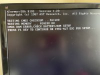
IMG_3974.jpg


The machine is using an AST XFormer/286 BIOS version 1.2.

I checked several websites to find explanation of the CMOS checksum error, which localized the error to one of five different problems being:

1. Use the Setup Command as specified on screen as shown in the picture, IMG_3974.jpg. When I try to run the setup as shown in image, IMG_3982.jpg.
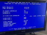
IMG_3982.jpg

I entered the minimum requirements of the date, time and the floppy's. The controller is a 16-bit WD1006A-MM2 floppy/hard drive controller combined (Note: controller came with the machine.). According to AST's users manual an XT controller is 8-bit while a 16-bit controller is AT so I left the XT floppy controller as 'no' with the entries as 360KB/1.44MB. Then pressed F10 followed by an F5 to confirm. After executing the F5 the clock stops and pressing F1 does nothing. It seems to hang the system. Of course, CTL-ALT-DEl resets it and the entries tried are not saved;

2. Restart the computer, which was ineffective;

3. Download and flash BIOS Update. I checked the web for AST BIOS to see if there was a resource where the BIOS could be downloaded from this type of motherboard. So far, I have not found either the existing BIOS or any update.

"Here is where I would ask the forum if there is a site where the BIOS could be acquired? In fact, I don't know, which chip is used to house the BIOS;"

4. Reset the BIOS. I didn't see a jumper near the BIOS; but, I did see a jumper near the area where the CMOS/CMOS battery is located;

5. Replace the CMOS battery. I just replaced the battery. The battery for the AST is only 4.5 Volts as opposed to the IBM motherboard from the same machine, which is 6 Volts. Right now I have 4.5 volt battery connected.

Any other suggestions would be greatly appreciated.
 
Forget the BIOS business--the BIOS is complaining that the checksummed RTC RAM doesn't verify. What RTC chip does your board use? Have you verified that all traces are intact (i.e. has there been any battery damage to the board?) Have you checked to see that the battery is getting through to the RTC chip?

If the board uses the MC146818, check the voltages at the chip; it may need replacement.
 
Last edited:
The battery for the AST is only 4.5 Volts as opposed to the IBM motherboard from the same machine, which is 6 Volts.
The IBM AT can also use 4.5 volts; it's just that IBM supplied a 6 volt battery (having the advantage of lasting longer than a 4.5 volt one).

Right now I have 4.5 volt battery connected.
How confident are you that you haven't reversed the connection ?
 
What RTC chip does your board use?
My guess is that the OP will not know. There is a low-res photo of the motherboard at [here]. I cannot see any 24-pin chip sized like the MC146818 or equivalent.

Have you checked to see that the battery is getting through to the RTC chip?
If the board uses the MC146818, check the voltages at the chip; it may need replacement.
@alejack12001: Does the motherboard have an 82C206 chip on it? If so, per [here], you should measure about the battery voltage on the Vcc pin of the 82C206 chip. I used "about" because we expect a diode or two to 'drop' some of the battery voltage. Be very careful not to short out the 82C206's pins.
 
First, the enclosed picture shows what the battery was connected to when I received the machine. I was using that as a guide since the motherboard doesn’t designate + or - on the battery connector. I used the red near the keyboard connection while the black was in the direction of the CPU.
0B06ED4A-471C-441B-8E97-8A07ED354A20_1_105_c.jpeg

Chuck(G) if the error is a RTC then it is part of the 82C206 CHIPs chip that is on the motherboard. According to the spec regarding the 82C206 houses both CPU and AT Bus clocks as well as the CMOS. So, this can’t be fixed.

PC CHIPS.jpg

The CHIP as shown in the picture is soldered down to the motherboard and with my Parkinson’s would never be able to get it up or replace it. So, I have big paper weight on my desk, I guess.
 
I have a few AST Premium/286 machines I've recently spent a lot of time working on. Just offering some data, my machines will give me the same error whenever I don't have a battery connected to the board (3.6V in my case). But if you just hit F1 and ignore the errors the machine will boot fine. And I never have seen a freeze/hung system upon saving BIOS settings. It sounds like the problem is you are being forced to save/update BIOS settings and the save process is what hangs?
 
Modem7: I up loaded a partcial part of the AST Xformer/286 motherboard manual that I have. It doesn't really show which end the CMOS battery positive connection is located other than a clear block with a shaded block at J something 4 at the top of the drawing near the glass diodes. So sqpat could suggest where the CMOS battery connects that would clear up some questions when the systems is powered down. The circuit diagram modem7 provided was helpful however the VCC for the 84 pin 82C206 is pin 32 not 4. Four is IRQ1 according to the diagram. Where did you get the circuit diagram for the VCC for the 82C206 chip? Is this something you mapped on your own from previous experience or from a manual?

sqpat: I initially tried the F1 strike to bypass the setup. The strike of the F1 was ignored and the only thing that worked of course was the CTL ATL ESC, which of course the setup couldn't be saved. Since you have had several of the AST Xformer/286 motherboards, do you have better manual or diagram of the motherboard? If the F1 worked for you, did you use the ASTUTE to configure the setup for the machine?

I am going to test this board again this afternoon with regard to the battery power connections using modem7's circuit board diagram to see if one of the transistors is failing. I write down the voltages and share them with you to see if you agree.
 

Attachments

  • AST Xformer286 - User's Manual Battery Connectiion.pdf
    622.4 KB · Views: 8
Caluser2000: The motherboard isn't marked as to 1 or + symbol. The manual that I uploaded concurs with the picture uploaded earlier where the red wire is close to the keyboard connector; at least from my perspective..

I just came from measuring the voltage of a diode near what would be pin 1 of the backup battery block. Its voltage measured 4.51 Volts. Between the diodes the voltage drops a little to 4.39 volts and on the opposite side of the diode, which is connected to VCC of 82C206 the voltage is 4.27 volts.

The F1 command seen at the startup seems to freeze the screen when depressed. I am thinking that my keyboard is probably the reason for the freezing. I have an IBM PS/2 keyboard attached with an adapter for the 5-pin din used with this type of machine. Keyboard may be sending the wrong signal associated with the F1 execution. I have a little problem finding these 5-pin din keyboard; they are quite expensive.
 
Personally looking at the pic the wires should be reversed. No shading over the pin facing the direction of the kb connector.
 
Last edited:
Pick a convenient motherboard ground, say the shell of a parallel-port connector. That will be negative--see which pin on the battery motherboard header that corresponds to. (i.e. use a continuity test on your DMM).
 
Thank you, ChucK(G) for the auggestion. I did the continuty test between pin 4 and ground and sure enough its showing that pin 4 is grounded where as I tried the pin 1 and got no response at all. So the picture is right the red cable is connected to the pin nearest to the keyboard connector and the black is connected nearest to the 82C206 chip.
 
The circuit diagram modem7 provided was helpful however the VCC for the 84 pin 82C206 is pin 32 not 4. Four is IRQ1 according to the diagram. Where did you get the circuit diagram for the VCC for the 82C206 chip? Is this something you mapped on your own from previous experience or from a manual?
The image that I pointed to in post #4 is taken from the datasheet of the OPTi 82C206, and shows the Vcc pin being pin 32.

The partial circuit diagram in the image is a suggestion to motherboard designers, and the same circuit diagram appears in the 82C206 datasheets from Chips and UMC.
To prolong the life of the battery, the two transistors and associated resistors provide +5V power (or whatever the motherboard's Vcc is) to the 82C206 when the motherboard is powered on.

I am going to test this board again this afternoon with regard to the battery power connections using modem7's circuit board diagram to see if one of the transistors is failing. I write down the voltages and share them with you to see if you agree.
On the 82C206's Vcc pin:
* With the motherboard powered on, expect something very close to +5V.
* With the motherboard powered off, expect the measured battery voltage minus the drop of the diodes.

Expect to measure the same on the 82C206's PSRSTB# pin.

The voltage drop over the two diodes will vary with battery voltage. If AST have used two 1N4148 diodes, as suggested, expect up to about a volt.
 
Modem7: sorry for the miss understanding of the pins associated with the 82C206 chip. Yes, I, too, found the datasheet for this chip. As I entered before, the battery was supplying 4.51 volts and dropped to 4.27 volts less the drop on the dual inline diodes. I haven't tried the voltage with the machine powered 'on' as yet. I'll post that reading and the PSRSTB# reading when I get a chance.
 
sqpat: I initially tried the F1 strike to bypass the setup. The strike of the F1 was ignored and the only thing that worked of course was the CTL ATL ESC, which of course the setup couldn't be saved. Since you have had several of the AST Xformer/286 motherboards, do you have better manual or diagram of the motherboard? If the F1 worked for you, did you use the ASTUTE to configure the setup for the machine?

Sorry, to be clear I had the AST Premium/286 - a different model from AST and with a previous chipset (CS8220 based). But in my experience, I can put anything (even incorrect values for floppies, hard drive settings, etc) into the BIOS and save the settings and boot fine. I had other problems getting the machines to POST originally, but once that was solved the BIOS screen never really caused me trouble. So maybe there is a bad chip or an electrical problem.

I never did much with the AST diagnostics for my machines. They didn't really seem to unlock any hidden features or anything like that.
 
I powered on the system and took measurements at pins 75, 32 and 15 which releated to VCC and PSRSTB#. With the system powered, the VCC and PSRSTB# recorded 4.93 volts. So, P82C206 is getting adaquite power to activate the chip. Suggestions?
 
I powered on the system and took measurements at pins 75, 32 and 15 which releated to VCC and PSRSTB#. With the system powered, the VCC and PSRSTB# recorded 4.93 volts. So, P82C206 is getting adaquite power to activate the chip. Suggestions?
Reading the 82C206 datasheet, perhaps measure the PWRGD pin, expecting a logic high.

1651101352495.png
 
Chuck(G): I cannot get to command line. F1 will not continue as was suggested by sqpat. If I could get to command line then diagnostic software could be employed. Only course of action is to CTL, ALT, ESC to get you to the setup, which freezes if adjusted. Modem7's suggested PWRGD being low may explain inactivity of the F1. I am going to measure again.

I was suggested that I remove everything from the machine including memory chips just leaving 64 KB then try again. His suggestion focused on either memory chip or hardware like floppy/HD controller effecting the system boot. He also suggested I check my capacitors; however, they are mounted all the way down on the MB and I don't have schematic of motherboard wiring.
 
Back
Top