• Please review our updated Terms and Rules here

AST XFormer/286 BIOS Checksum error

Chuck(G): I cannot get to command line. F1 will not continue as was suggested by sqpat. If I could get to command line then diagnostic software could be employed. Only course of action is to CTL, ALT, ESC to get you to the setup, which freezes if adjusted. Modem7's suggested PWRGD being low may explain inactivity of the F1. I am going to measure again.

I was suggested that I remove everything from the machine including memory chips just leaving 64 KB then try again. His suggestion focused on either memory chip or hardware like floppy/HD controller effecting the system boot. He also suggested I check my capacitors; however, they are mounted all the way down on the MB and I don't have schematic of motherboard wiring.
Actually, the 360 floppy and controller along with the video card are the only cards operational in the machine. In addition, the motherboard memory minimum is 256 KB soldered to the board. The remaining 768 KB are removable.

I was also suggested to check the power supply voltage. Question on this suggestion: Can you lift the connectors off the motherboard to check the voltages? Was it modern or these older power supplies that required the power to be connected because of a switch trigger embedded?
 
Those kinds of hardware problems would make sense if you had trouble with POST or booting, but you POST fine and don't know if boot works (due to the BIOS). Since you POST fine I would doubt the PSU is the problem.

I wonder if it is possible to write a BIOS program to test the CMOS memory? It's not something I have ever had to deal with. But nonetheless if you had an EPROM programmer it might open the door to a few other things you could try.
 
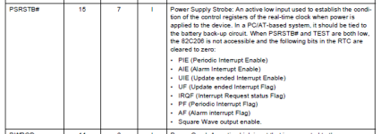
I remeasured the voltages for the P82C206 Chip and found that VCC pins 75 and 32 were registering 4.96 Volts with the power on. The battery lower results at 4.29 Volts for the same two pins. The PSRSTB#, pin 15, still shows 4.96 volts. I stripped the RAM chips off and reseated them with no change in the error displayed following POST other than POST stating there was a checksum error associated with the CMOS RAM as initially posted. I measured the P8 and P9 connections with the following results:

P8 Red 5.06 Volts P9 Blk, Blk gounds
Blank no connection White 5.03 Volts
White 12.01 volts Red 5.01 Volts
White -11.84 volts Red 5.00 Volts
Blk, Blk grounds Red 5.01 Volts
Note: My connections were discolored so actually the red were more orange in color and the whites were more yellow in color.

Chuck(G): The ROMs used with the AST XFormer/286 are 27128 chips. One even and one odd about like the AT&T 6300 except being larger in size. There are sockets for added ROMS, which are listed as optional. According to the AST XFormer/286 users manual, I can have combinations of standard 27128 or 27256 chips to house the ROMs. The users manaul doesn't mention a diagonstic ROM however. Of course, the manual is a general purpose manual not a service manual, which I can't find.

I have a ROM burner and can get the 27128 chips. So, if there is a ROM that has a diagnostic, I wouldn't know where to look. I tried Howard Sam's to see if they had a photo fact on the AST XFormer/286; but that was a no go from their reply to my inquiry.

I do have a diagnostic disk that was released in 1995 by AST under release 2.23 for AST PC's and written as "AST Advanced Diagnostics is a systems diagnostic tool designed primarily for use on AST computers. To run it properly, you must boot the disk image." I looked into the image file and saw one exe followed by a number of rsm/rsx files; but, none seemed to be directed to the CMOS; most dealt with peripherals such as SCSI, floppy, IDE, mice, VGA, memory, and etc. Plus the text files were specifically addressing AST machines and not motherboards.

So again, I don't know where to look for ROM specific diagnostic tool for this motherboard.
 
Modem7's suggested PWRGD being low may explain inactivity of the F1. I am going to measure again.
Did you do that measurement ?

I measured the P8 and P9 connections with the following results:
That matches what is used in the IBM PC and IBM XT, with one exception: I suspect that your "White 5.03 Volts" should have been "White -5.03 Volts".

By the way. Your "P8 Red 5.06" is a POWER GOOD signal, and if AST implemented the recommended 82C206 design, that POWER GOOD signal is what is expected to be on the PWRGD pin of the 82C206.

I do have a diagnostic disk that was released in 1995 by AST under release 2.23 for AST PC's and written as "AST Advanced Diagnostics is a systems diagnostic tool designed primarily for use on AST computers. To run it properly, you must boot the disk image." I looked into the image file and saw one exe followed by a number of rsm/rsx files; but, none seemed to be directed to the CMOS; most dealt with peripherals such as SCSI, floppy, IDE, mice, VGA, memory, and etc. Plus the text files were specifically addressing AST machines and not motherboards.
Of no use anyway, because you cannot floppy boot.

But had you been able to boot, the AST Xformer/286 User's Manual points to particular diagnostics software, 'ASTUTE'.
See page A-6.
ASTUTE is on the AST Xformer/286 Setup Disk at [here].
 
The Supersoft diagnostic ROMs should pick up malfunctioning CMOS RTC, I'd imagine.
I have a ROM burner and can get the 27128 chips. So, if there is a ROM that has a diagnostic, I wouldn't know where to look.
So again, I don't know where to look for ROM specific diagnostic tool for this motherboard.
minuszerodegrees.net
Think Chuck was referring to these diagnostic roms.
After having read the general information at the pointed-to web page, use the 'Click here for the IBM 5170' link at the bottom of the page.
That link will take you to a second web page that is about the AT-class version of the Supersoft/Landmark Diagnostic ROM's
The second web page is targeted at the IBM AT (IBM 5170), and that is why the odd and even ROM images (binaries) are for 27256 (or 27C256) sized EPROM's.
Because you want to use 27128 for your AT-class AST computer, use the 27128 sized odd and even ROM images at [here] and [here].

(BTW. The 27256 sized images are simply the 27128 sized ones that have been 'doubled-up'.)

As you will read, the Supersoft/Landmark Diagnostics are not expected to work with VGA, and so you will be relying on error beeps that you hear from the speaker.
Beeps for the AT version of the diagnostics are explained on pages 40 and 41 of the user manual.
 
Did you do that measurement ?


That matches what is used in the IBM PC and IBM XT, with one exception: I suspect that your "White 5.03 Volts" should have been "White -5.03 Volts".

By the way. Your "P8 Red 5.06" is a POWER GOOD signal, and if AST implemented the recommended 82C206 design, that POWER GOOD signal is what is expected to be on the PWRGD pin of the 82C206.


Of no use anyway, because you cannot floppy boot.

But had you been able to boot, the AST Xformer/286 User's Manual points to particular diagnostics software, 'ASTUTE'.
See page A-6.
ASTUTE is on the AST Xformer/286 Setup Disk at [here].
Regarding the White 5.03 volts, yes, it was -5.03 volts. I wrote it down but forgot the minus sign. I have the setup disk. I think you initially provided link.
 
After having read the general information at the pointed-to web page, use the 'Click here for the IBM 5170' link at the bottom of the page.
That link will take you to a second web page that is about the AT-class version of the Supersoft/Landmark Diagnostic ROM's
The second web page is targeted at the IBM AT (IBM 5170), and that is why the odd and even ROM images (binaries) are for 27256 (or 27C256) sized EPROM's.
Because you want to use 27128 for your AT-class AST computer, use the 27128 sized odd and even ROM images at [here] and [here].

(BTW. The 27256 sized images are simply the 27128 sized ones that have been 'doubled-up'.)

As you will read, the Supersoft/Landmark Diagnostics are not expected to work with VGA, and so you will be relying on error beeps that you hear from the speaker.
Beeps for the AT version of the diagnostics are explained on pages 40 and 41 of the user manual.
i did download the Supersoft/Landmark Diagnostics, which appear to be 33 KB for each. I guess I will have to record the beeps as my video card is Paradise VGA Plus PVGA1A. So, according to the multiple web pages the card will not display anything.

So, let me understand this correctly, The EPROM will house for each 27128 odd or even ROM image plus the odd or even Supersoft/Landmark diagnostics, which are substituted for the existing 27128's on the AST motherboard. Is that correct?
 
Yes remove the existing bios, and install the supersoft one.
 
... The PSRSTB#, pin 15, still shows 4.96 volts.
That is a good sign that the capacitor on the PSRSTB# pin (see [here]) is operational. With the computer remaining off, in time, the voltage there would move to 4.29 V. You do not need to check that.

(From your measurements, we know that the resistor on the PSRSTB# pin is okay.)
 
4. Reset the BIOS. I didn't see a jumper near the BIOS; but, I did see a jumper near the area where the CMOS/CMOS battery is located;
The CMOS/RTC portion of the 82C206 can be reset.

The document at [here] suggests that one simply shorts the 82C206's Vcc pin to ground (presumably whilst power off and battery removed), but there is risk of damage.
I think better would be to:
1. Power off the motherboard.
2. Remove battery.
3. Wait until the 82C206's Vcc pin drops to near 0V.
4. Verify that the TEST pin is near 0V.
5. Verify that the PSRSTB# pin is near 0V.


1651214693200.png

1651214945636.png

1651215190860.png
 
After receiving the odd/even ROM binaries for the IBM 5170 and the Supersoft diagnostic, I noticed that the that the IBM 5170 was using a twice as large BIOS ROM chip namely 27256 as opposed to 27128 or more accurately 27C128 chip housed on the AST XFormer/286.

I pulled the BIOS ROM chips from the motherboard and found that they must have been EPROM's burned by the previous owner of the computer. The labeling on the chip for the "odd" is JL27C128D/029031. There is no datasheet for this chip other than the 27C128, which is the default data sheet for numerous labels of the chips such as for the "even," which was L27C128D/047010. The "odd" chip was made in Singapore in 2009 while the "even" was made in Japan 2013.

I was able to read the chip using the default label 27C128 using a GQ-4x4 reader/writer for EPROMs. Both the even and odd chips are 16KB in size and show an Award Software copywrite dated 1984 and 1987 at the beginning of the listing. I saved copies of the binaries odd/even on my laptop as I would want the original BIOS restored after the test of the Supersoft diagnostic.

Questions came to my mind regarding the development of the BIOS as to why Award software was used to produce the BIOS, rather than AST itself since AST engineers developed the board as a replacement for the IBM 5162 PC XT/286 motherboard? Is there a way to reverse engineer the BIOS binary to ASM to see if it was made too generic for the board? Meaning that maybe the developers of the BIOS didn't accomidate for two DMA chips built, for example, in to the P82C206 CMOS chip. According to the AST XFormer/286 user manual the bios 27256 could be used as the bios instead of the 27128 chip. Would this mean that the IBM 5170 BIOS be supported since it is twice the size of the Award Bios found on the 27C128 chip? Would it work?
 
AMI, Award and Phoenix were the big BIOS vendors. It would not have been worthwhile for AST to produce their own.

There's always a BIOS ID that identifies the vendor and model for the BIOS. It's usually displayed at the opening screen.
 
I remember the Award always identified the processor, co-processor if any, RAM, extended or expanded RAM, BIOS, date and time about one-half of the screen. Always at the end of the POST and just before the boot of the OS. I remember seeing these on my 386SX a long time ago. Later the energy sysbol was displayed showing the machine was supposed to be energy consensus. Thanks for taking me back down memory lane. I remember there was always a big push for Phoenix BIOS as well. Okay, I understand.
 
Just as another data point, my AST Premium 286 BIOSes were also modified award BIOSes. Sometimes they were referred to in marketing materials as AST and sometimes Award, it seemed to change depending on version.

It would be nice if you uploaded those BIOSes here too - I uploaded mine in another thread last month since no one had ever uploaded them. I know there are sites that archive these around and you might be doing the next guy with your same machine a favor. (I think they might have to be attached as a zip)
 
Chuck(G): there is a bios chip near the keyboard connector on the AST. Yes, I should pull that one and back it up as well.

Sqpat: Yes, I could do that to upload my backed off BIOS from the AST XFormer/286 as well as the keyboard since Chuck(G) mentioned it. Trixter used to keep all these old school machines on his ftp site. I don't know if he's taken it down; I haven't been able to access it in a while.
 
The keyboard controller BIOS on 286 era systems is usually programmed into the controller itself and so not readily readable. However, I don't know your system.
 
Back
Top