• Please review our updated Terms and Rules here

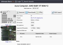
AUVA JUKO Baby XT BXM-10

fdiskitup

Experienced Member
Joined
Mar 2, 2022
Messages
247
Location
Chicagoland, USA
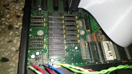
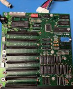
My baby just goes waaaaaaah continuously when I power it on ! (Continuous tone from the speaker when I flip the power switch)

D3C90CA6-CADE-4B9B-A83D-94C845FB9558.jpeg

Things I have tried:
1, extract, deoxit, re-seat all ram chips, CPU, Bios chip.
2, tried a different power supply.
3, post diagnostic card gives voltages on the isa as ok.
4, minimum memory configuration with only 256k, 2 chips in bank 0. Swopped chips bank 0 with bank 1.
next steps ?
try another cpu or bios chip ?
 

Attachments

  • CE202125-2F65-40F3-A0D0-E4E2F4BA3426.jpeg
    CE202125-2F65-40F3-A0D0-E4E2F4BA3426.jpeg
    330.3 KB · Views: 23
The continuous tone is sometimes a sign of a motherboard that is not starting.

Your POST card does not show the status of the POWER GOOD signal from the power supply (something required to start the motherboard). Although you have tried two power supplies, it wouldn't hurt to measure the POWER GOOD signal per [here].

... try another cpu or bios chip ?
Why not?

As for the BIOS chip, it turns out that I have pretty much the same motherboard, unlabelled and limited to 640 KB: Manual, photo and an image of the BIOS ROM in the fifth entry down at [here]. There are people/companies at [here] who can use the BIOS ROM image to create a ROM for you.

... next steps ?
Perhaps verify that:
* The reset pin (pin 21) on the V20 CPU is at a logic LOW (i.e. CPU not being held in the reset state).
* The clock pin (pin 19) of the V20 CPU is receiving a clock. A logic probe will provide good confidence of that.
 
If you're going to try another BIOS, and don't have another at hand, you can try this one: https://www.phatcode.net/downloads.php?id=101
I think Nec V-20 CPU is the last thing to check, because they're tough. Even 8mhz version are running fine at 12mhz!.
You tried with ONLY power and Speaker?.. No keyboard, no video...

Try this memory configuration. All my Juko ST's are running fine with 1mb in this position.
Switch 3&4 off for 1mb config.
WhatsApp Image 2022-08-16 at 11.20.54 AM.jpeg
 
Last edited:
Try this memory configuration. All my Juko ST's are running fine with 1mb in this position.
Member Ruud posted a photo of his motherboard at [here], which shows that his motherboard also has the associated parity chips (4 of) fitted (requiring that switch 1 be set appropriately).
 
I have this board as well, and it was working perfectly fine when I bought it around 2015 or so. But lately it won't start from cold start, but if you flip power supply off and on, it works fine. It's not power supply, as I tested it with multiple power supplies that work great with other boards.

At one point I tried to switch the 24mhz xtal for a 30mhz, and ram from 100ns to 60ns. I hoped it may work at 15mhz, but it didn't, so I reverted to original xtal and memory.
 
I have this board as well, and it was working perfectly fine when I bought it around 2015 or so. But lately it won't start from cold start, but if you flip power supply off and on, it works fine. It's not power supply, as I tested it with multiple power supplies that work great with other boards.
If you want assistance with that , you should start a new thread, otherwise two threads running through this thread will confuse people like me.
 
Additional troubleshooting:
Checked solder joints on cpu, bios, memory.
Checked the power supply connected. All voltages are good,
power good = 5.1v
12v,-12v, G, -5v, 5v all checkout ok.
With the board disconnected, only +5V gives a measurable resistance 430ohms to ground.
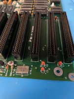
Checked orange tantalum caps - did not find a smoking gun.
One tant C3 has resistance off the range. Desoldered replaced, still off range with new capacitor in place.
4F929EB9-ECEE-4902-B2D5-76D4C7266E8B.jpeg

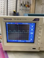
Clock signal on the cpu pin 19 looks good.? Ok im learning to use the scope..but theres a clock signal. F77E60D6-4EC1-4D1F-B2E6-8DA6417BDA43.jpeg

Can i flash a new bios with my xtide card ?
28C64 to replace 2764?
 
Cpu checks with the oscilloscope
Pin
1 ground - no activity
2 to 8 (A14 to A8) - activity
9 to 16 (AD7 to AD0). - activity
17 (NMI) - no activity
18 (INTR) - no activity
19 clock - ok, fast
20 no activity
21 (reset) no activity
22 (ready) active
23 (test ) no activity
24 to 27 (INTA, ALE, DEN, DT) active
28 to 31 (IO, WR, HLDA) no activity
32 (RD) active
33,34 (MW, SSO)no activity
35 (A19) active
36 (A18/S6) no activity.? Only address line with no activity.
37, (A15-A17) 38, 39, active
40 vcc no activity
 
On the bios chip
Pin
1=(Vpp) no activity
2= (A12) Pulses but much lower than any other signal.
All the rest are either active and normal looking, or inactive.
 
power good = 5.1v
12v,-12v, G, -5v, 5v all checkout ok.
Checked orange tantalum caps - did not find a smoking gun.
One tant C3 has resistance off the range. Desoldered replaced, still off range with new capacitor in place.
1. Good capacitors are expected to have 'resistance off the range '.
2. When measuring components in-circuit (in-circuit = not removed from board), often you are measuring multiple components at the same time.

Without further education on electronics, give up on investigation of the tantalum capacitors. If one (or more) had gone short-circuit, your power supply would be in a shut-down state, not producing output voltages.

Clock signal on the cpu pin 19 looks good.? Ok im learning to use the scope..but theres a clock signal.
The clock period is approximately 200 ns, and so the frequency is approximately 5 MHz (the standard 4.77 MHz ?)

Odd that the frequency is showing as approximately 143 kHz. That may change to actual if you adjust the Volts/Div from 5.00V to 2.00V

2 to 8 (A14 to A8) - activity
9 to 16 (AD7 to AD0). - activity
35 (A19) active
37, (A15-A17) 38, 39, active
Suggesting that code is executing.

36 (A18/S6) no activity.? Only address line with no activity.
That may or may not be related to the problem cause. For example, if a fault resulted in BIOS code executing in a tight loop, then only some address lines may have activity.

Can i flash a new bios with my xtide card ?
28C64 to replace 2764?
Yes. To prove it, I did that, putting the 28C64 on my very-similar-to-yours motherboard.

If you have an MDA or CGA video card, see if Ruud's Diagnostic ROM displays anything.
Get the 8 KB sized binary file for the 28C64 from:
1. Go to http://www.minuszerodegrees.net/ruuds_diagnostic_rom/Ruuds Diagnostic ROM.htm
2. Click on the 'here' for the first 'IBM 5150 motherboard option'.
3. In the 'Images (content) ...' section at the bottom, select one of the 8 KB sized downloads.

(Ignore references to an adapter, because the web page targets the IBM PC.)
 
Thank for sticking with me, I really appreciate the time and effort put into your replies.
If you have an MDA or CGA video card, see if Ruud's Diagnostic ROM displays anything.
Does it really need MDA or CGA ? I dont have a anything other than vga cards, (or monitors), mostly 16 bit isa, I can borrow from my 5160 (ati wonder with bus mouse port).

“Ruud's diagnostic ROM requires an MDA or CGA video card. An EGA card or VGA card will not work.”
Thats my next step.. even if it wont display It should stop the continuous bleeping
 
If you can get yourself one of the devices shown at [here], that would be good. Per the 'Checkpoint codes' section of [here], if you have a parallel port addressed at 378h or 278h, then the device can show the 'checkpoint' codes outputted by Ruud's diagnostic ROM.

I can see some on eBay using search text of: lpt post
 
Cpu checks with the oscilloscope
Pin
1 ground - no activity
2 to 8 (A14 to A8) - activity
9 to 16 (AD7 to AD0). - activity
17 (NMI) - no activity
18 (INTR) - no activity
19 clock - ok, fast
20 no activity
21 (reset) no activity
22 (ready) active
23 (test ) no activity
24 to 27 (INTA, ALE, DEN, DT) active
28 to 31 (IO, WR, HLDA) no activity
32 (RD) active
33,34 (MW, SSO)no activity
35 (A19) active
36 (A18/S6) no activity.? Only address line with no activity.
37, (A15-A17) 38, 39, active
40 vcc no activity
WR no activity? Really!

Stuck trying to read from memory (bios?)

Perhaps confirm that the chip select line on the bios chip is active or low.
Then check activity on all address and data lines on the rom.
 
Flashing various 8kb bios files suggested above did not change the continuous tone on startup.

I can take the V20 cpu from this board and put it in my 5160 board ? That would at least eliminate it from consideration.
 
If you can get yourself one of the devices shown at [here], that would be good. Per the 'Checkpoint codes' section of [here], if you have a parallel port addressed at 378h or 278h, then the device can show the 'checkpoint' codes outputted by Ruud's diagnostic ROM.

I can see some on eBay using search text of: lpt post
Would this work if the lpt port is on a multi io isa-8 card ?
Ill try my existing post card with Rudds rom just for fun.
 
Flashing various 8kb bios files suggested above did not change the continuous tone on startup.
My hypothesis about the cause of the 'continuous tone' symptom on an IBM 5150/5160 (if experienced) is at [here]. If that is correct, then on an IBM 5150/5160 exhibiting the 'continuous tone' symptom, the symptom would not disappear until the computer was repaired to the point where not only is the motherboard's power-on self test (POST) starting to get executed, but then POST execution gets at least as far as the point that the PB1 pin on the 8255 chip gets configured to output a LOW.

In regard to your clone motherboard, whatever code there is in the ROM that you fit, might be starting to execute, but just not executing far enough in the code to sufficiently configure the 8255 (which on your motherboard, will be within the flatpack chip).

I can take the V20 cpu from this board and put it in my 5160 board ? That would at least eliminate it from consideration.
Yes, try that.

Would this work if the lpt port is on a multi io isa-8 card ?
It will if the port is configured to start at 378h or 278h (the LPT ports that Ruud's diagnostic ROM outputs to). The card's documentation should reveal the answer.

Ill try my existing post card with Rudds rom just for fun.
If that is a modern POST card, then it is not expected to show the 'Ruuds diagnostic ROM' codes on an XT-class motherboard, such as yours.
The parallel (LPT) port POST code reader is the way to go for Ruud's diagnostic ROM.

$9.50 for the parallel port post code tester including shipping - bargin !
Now we wait for the post….
Until then, there are some things to try. Do you have the ability to ground a pin in an ISA slot (connect it to ground) ?
 
POST would be prevented if there is a signal issue at the ROM.
If the processor is SOLELY reading, then it is very likely that it is trying to run code from the BIOS chip.

- if the chip select signal(s) are going active at the ROM, good sign
- I would then check that all 8 data lines at the ROM are toggling and have good looking signals
- lastly check that the address lines are sensible. Not all must be toggling, but when you power cycle it is likely that you will see at least some edges on every address line.

I would look for signals that can't be verified to have activity at the ROM. If such a problem exists, you can probably trace it out and figure out where the defect might be. broken track, dead bus driver I/O.. something like that.
 
On the bios chip
Pin
1=(Vpp) no activity
2= (A12) Pulses but much lower than any other signal.
All the rest are either active and normal looking, or inactive.
Is this socket compatible with 27C256?
You should see activity on all data lines.
You should see the chip select line toggling.
You should be able to verify that all address lines CAN toggle. If at steady state you can't see any one address line toggling, then try power cycling to see if you get a burst of toggles. If an address line = +5V, 0V, or has a distorted shape - look at the bus driver chip.
On the data lines, this is more tricky because they are bi-directional. I would look for clean edges and well formed data pulses; if there is an abnormal distortion that might indicate a problem. By abnormal I mean - different than the other 7 data lines.
 
Back
Top