• Please review our updated Terms and Rules here

Cbm dual drive 3040 disk - two red lights

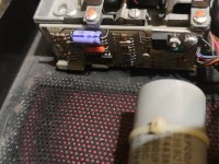
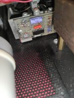
Pictures - excellent.

+12VA and +12VB look good.

We can work around the lack of reset button on the PET I think...

Can you remind me - when we tried to format drive 0 and drive 1 - did your see the disk select activity LED illuminate for drive 1 as well as drive 0?

You only got the drive 0 motor to work didn't you?

Dave
 
Can you remind me - when we tried to format drive 0 and drive 1 - did your see the disk select activity LED illuminate for drive 1 as well as drive 0?
yes i can see led for both drives but i can hear spinning only for drive 0 :(
 
OK,

Can you measure the logic level on disk drive IC UM3 (6522) pins 14 and 15 after you have reset the drive please. They should either both be HIGH or both be LOW. These are the two "MOTOR ON" signals. Pin 15 is for drive 0 and pin 14 is for drive 1. They do go through a bit more logic before they actually get to the disk drives themselves - but let's check to see if we are getting any sense out of UM3 first shall we.

Report the static values of UM3 pins 14 and 15 back to me after a disk drive reset.

Enter the following sequence of commands into the PET:

10 OPEN 1,8,15
20 PRINT #1,"N0:DER,42"
30 CLOSE 1

Measure UM3 pin 15 (motor on signal for drive 0) and RUN the above program. The pin should change state, the LED on drive 0 should illuminate and the motor should run?

I hope that the drive stops eventually and the LED goes out? Does the PET return to READY?

If so, change line 20 to:

20 PRINT #1,"N1:DER,42"

Reset the disk drive logic.

This time measure UM3 pin 14 and RUN the program.

What happens?

Dave
 
Can you measure the logic level on disk drive IC UM3 (6522) pins 14 and 15 after you have reset the drive please.
i am desperate!!! I can't do this because UM3 is under RRIOT replacement board! :(
 
>>> i am desperate!!! I can't do this because UM3 is under RRIOT replacement board!

I shouldn't have to tell you this now - but look at the schematic diagram and you will observe that UM3/15 is connected to UE6/3 by a copper track and UM3/14 is connected to UE6/9 with a copper track.

If you can't measure the signals at one place - try another point that is the same signal...

UE6/3 is the motor on signal for drive 0.
UE6/9 is the motor on signal for drive 1.

No need to be desperate - see?

I recon both signals should be HIGH after a reset. They should be active LOW.

Dave
 
Measure UM3 pin 15 (motor on signal for drive 0) and RUN the above program. The pin should change state, the LED on drive 0 should illuminate and the motor should run?
Yes, i run the program and i measured UA6 PIN 3, the signal turns LOW for a few seconds then turns HIGH and the drive stops, the drive led turns off and the central one lights up.
If so, change line 20 to:

20 PRINT #1,"N1:DER,42"

Reset the disk drive logic.

This time measure UM3 pin 14 and RUN the program.
I measured UA6 PIN 9 but on this pin i have always HIGH signal!
 
>>> Sorry, UE6!

Just checking...

So that probably accounts for why the second drive's motor is not running - the /MOTOR ON 1 signal is not activating from the 6522 IC UM3.

I know you swapped UM3 over the other day - but what is the state of what you put into there?

Dave
 
>>> Sorry, UE6!

Just checking...

So that probably accounts for why the second drive's motor is not running - the /MOTOR ON 1 signal is not activating from the 6522 IC UM3.

I know you swapped UM3 over the other day - but what is the state of what you put into there?

Dave
It is used :(
 
>>> It is used

This is the problem - is it used but good or used but bad?! You may have swapped one faulty IC for another one...

There is a way to test to see if the drive motor is working by swapping the two black connectors over on the rear of the analogue board and trying to format drive 0 again. This will still operate the drive 0 motor on signal - but we will have plugged the other drive in instead.

EDIT:

>>> I changed three different 6522 but i have always same situation...

In that case it is probably not the 6522 then...

Dave
 
If you read my last post we can test for that...

There is also a small circuit board on the rear of each disk drive. This is the motor speed controller.

The actual drive (and the motor controller) should be a Shugart SA400 - but with the controller board missing. See https://deramp.com/downloads/floppy_drives/shugart/SA400 Service Manual.pdf. I suspect that the TRACK 0 microswitch and INDEX opto sensor is missing also.

Dave
 
I have these little board between drive..
 

Attachments

  • 1664218467163..jpg
    1664218467163..jpg
    3.6 MB · Views: 5
  • 1664218510920..jpg
    1664218510920..jpg
    1.4 MB · Views: 5
>>> And where are these???

They are not required...

Shugart produced a 'standard' SA400 disk drive that people would purchase and interface to.

The likes of Apple and Commodore (and others) wanted to make things cheaper - so the electronics PCB was removed from the drives - and other modifications may have been done as well. The one board (sitting on top of the left hand drive) largely replaces the functionality of the two boards that would exist on the two drives... Hence cheaper.

The TRACK 0 microswitch could have been removed on the basis that you could "assume" that the head was over track 0 if you always moved it out by 40 tracks when you initialise the drive for the first time. This (generally) causes a horrible noise to start with as the head tries to move further than it is permitted to do!

>>> I have these little board between drive..

These little boards are the motor speed controller. They take the /MOTOR ON signal and switch the motor on. The motor has an inbuilt tachometer that goes to the little board - and this then provides the speed control.

There is another way of testing drive 1. Apply a small wire link between UJ6 (SN7406) pin 10 and 0V/GND. This should turn the motor on to drive 1.

I am going to call it a night now.

Dave
 
Back
Top