• Please review our updated Terms and Rules here

Cbm dual drive 3040 disk - two red lights

Hmmm. It would be strange to have two (2) faults on exactly the same signal...

Let's call it a night for today. I suspect we are both getting tired now...

Dave
 
I still have some more thoughts, but been busy today, going out tonight, and will be busy tomorrow morning.

Get back to you tomorrow afternoon.

Dave
 
I think the focus will now shift to the disk drives and the analogue board itself.

We will need the following manuals:

https://deramp.com/downloads/floppy_drives/shugart/SA400 Service Manual.pdf PDF pages 55 (drive electro mechanics) and 66 (speed controller).

http://www.zimmers.net/anonftp/pub/.../old/4040/2040-3040-4040_drive_schematics.pdf PDF page 10 (analogue board schematic).

If you look at the both of the pages of the SA400 drive, you will observe a number of interconnecting wires have colours associated with them. For example, the motor has RED, YELLOW, GREEN and BLUE. RED and BLUE are the motor supplies and YELLOW and GREEN are the tachometer. All of these cables go to the speed controller. The speed controller then has three (3) additional cables (BLACK, BROWN and ORANGE). These wires go to the black connector plugged into the analogue board. All of the other wires from the stepper motor, switches etc. also go to the black connector.

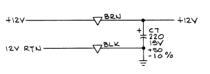
The BLACK cable from the speed controller is 0V/GND. The BROWN cable is +12V and the ORANGE wire is /MOTOR ON.

I 'think' the only parts on PDF page 55 that should be present and wired to the black connector should be the STEPPER MOTOR (2 * RED, ORANGE, BROWN, YELLOW and BLACK) and the WRITE PROTECT SWITCH (BLACK). There will be the DRIVE SELECT LED as well of course.

It would be worth checking the black connector, what coloured cables you have and where they are connected to. Double check this with the physical drive that you have. I don't think there is a TRACK ZERO switch fitted, the HEAD LOAD SOLENOID or the INDEX PULSE detector - but I may be wrong here.

We are not going to DO anything for the time being - but just document what we have.

The large black connectors on the analogue board that go to the disk drives contain two (2) rows. You can see from your first photograph in post #659 that the contacts are numbered from 1 to 15 on the top - but they are lettered on the underside. Ways 3 and 15 do not have gold contact fingers (or cables) but plastic latching arrangements. Hopefully, most of the signals we want to measure are on the 'numbered' side of the connector, but we need to determine this. You should be able to get your multimeter probes onto the bits of gold fingers that are protruding from the connector (providing you don't accidentally short one gold finger to an adjacent one that is).

How does this sound to start with?

Dave
 
Last edited:
Pins are numbered 1-15 on the disk drive connector. Pins 3 and 15 are not used.

The other side of the disk drive connector (the lettered side) will NOT be purely alphabetical. It is highly likely that some of the letters will be missing (following convention). I think the following letters are applicable (but this is a guess at this time):

Code:
1  A
2  B
3  C
4  D
5  E
6  F
7  H
8  J
9  K
10 L
11 M
12 N
13 P
14 R
15 S

Pins 3 (C) and 15 (S) are not used.

This is all an educated guess. Can you check it out on the PCB of the analogue board? I see the numbers marked on the component side. Is the silk screen on the solder side as well (detailing the letters) I wonder?

Dave
 
I did not understand what I have to do Dave ..... ask for a continuity test of the two cables with black connector? :(
 
No, just document what cables you have on the drive connector for the time being. What colour the cable is and which pin of the connector it goes to.

Have a look at the disk drive and see what equipment is fitted. We know there is a drive motor, a speed controller PCB, a stepper motor, a drive activity LED and a write protect switch fitted. These should be cabled up to the disk drive connector. Is there anything else on the drive that I haven't mentioned?

I have some tests we can then perform.

Dave
Yes..all seems correct! We can start with your test !
 
Have a look at the disk drive and see what equipment is fitted. We know there is a drive motor, a speed controller PCB, a stepper motor, a drive activity LED and a write protect switch fitted. These should be cabled up to the disk drive connector. Is there anything else on the drive that I haven't mentioned?
No nothing else Dave!
 
I have shut everything down for the night now.

I will post my tests tomorrow morning for you.

The first test is simple, and that is to measure the +12V power on each of the disk drive connectors. I am sure they will be OK, but best to test...

The remainder of the tests are with the disk drive connectors removed and to perform continuity tests on the stepper motor, write protect switch and the main drive motor. We can compare the results between the two drives. But I will post these tests tomorrow.

Did you find any markings on the solder side of the analogue PCB relating to the letters of the drive connector? Perhaps use a mirror and bright light to look.

Dave
 
OK.

The first test is to use your multimeter and check for 0V and +12V on each of the disk drive connectors (labelled as P1 and P8 on the analogue PCB). You should check these with the black disk drive connectors still plugged into the analogue board.

Put your BLACK lead on gold finger 14 (0V) and your RED lead on gold finger 13 (+12V). Please make sure you don't short the leads out - or accidentally short to the nearby gold fingers.

Report the voltages. I am expecting these to be correct though.

Dave
 
The next tests (until told otherwise) are to be conducted with the disk drive power OFF, the black disk drive connectors disconnected from the analogue board and your multimeter set to read resistance.

We will be measuring on the pins of the black disk drive connector NOT the fingers of the analogue board.

I will be referring to the pin numbers of the connector. These are on the edge of the connector that would make contact with the component side of the analogue PCB. The pin letters are on the opposite edge of the connector.

The first thing to do (to get us into the mood) is to check for correct operation of the write protect microswitch.

1664441951336.png

Measure the resistance between pin 4 (brown wire) and pin D (black wire) of each disk drive connector. With the write protect switch not operated you should get one resistance reading and with the write protect switch operated you should get a different resistance reading. One reading will be a short circuit and the other an open circuit. You may find it easier to insert a disk with no write protect tab on it and take a resistance measurement and then insert a disk with a write protect tab on it and take another resistance reading.

Dave
 
The next test is the stepper motor windings.

1664442288538.png

Measure the resistance between the following points of the disk drive connector and report the values back. We are looking for a similar resistance for each winding. Repeat the test for both disk drives.

Pin 12 (RED) and pin M (BROWN) - Phase C.
Pin 12 (RED) and pin P (BLACK) - Phase A.
Pin 11 (RED) and pin N (ORANGE) - Phase D.
Pin 11 (REd0 and pin R (YELLOW) - Phase B.

Also measure the resistance between pins 11 (RED) and 12 (RED). This reading should be a high resistance (as opposed to the others).

Note that the RED wires are connected to two (2) separate phase windings.

Dave
 
The next test is the motor.

1664442711951.png

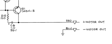
Is it possible to measure the resistance between the READ and BLUE leads of the motor? This will be somewhere on the little motor speed board.

The best place may be 0V/GND and the negative end of C6 (follow the PCB tracking back from the RED lead of the motor):

1664442827741.png

Beware, however, that the 0V/GND we are talking about is on the speed controller board and not the analogue board or logic board:

1664442913133.png

You may find it easier to follow the BLACK wire back from the speed controller board to the disk drive connector and use the pin of the disk drive connector. I am guessing that this will be pin 14 of the connector - but this is only an educated guess...

If you repeat these tests for both disk drives we can compare the results.

Where we go next will be dictated by the results...

Dave
 
OK.

The first test is to use your multimeter and check for 0V and +12V on each of the disk drive connectors (labelled as P1 and P8 on the analogue PCB). You should check these with the black disk drive connectors still plugged into the analogue board.

Put your BLACK lead on gold finger 14 (0V) and your RED lead on gold finger 13 (+12V). Please make sure you don't short the leads out - or accidentally short to the nearby gold fingers.

Report the voltages. I am expecting these to be correct though.

Dave
Good evening Dave!
Ok i have +12,2 V on P1 and P8
 
ou may find it easier to insert a disk with no write protect tab on it and take a resistance measurement and then insert a disk with a write protect tab on it and take another resistance reading.
Ok without disk inserted i read 1,6 ohm and infinite with disk protected (drive 0),
0,9 ohm and infinite with disk protected (drive 1).
 
Back
Top