• Please review our updated Terms and Rules here

CBM PET 3032 STRANGE BOOT

These are some things you could do while waiting for a new 74191:

Possibly the 74191 that you got that is reported bad is ok, and the tester is simply reporting it bad.

Have you checked both the 74191's (the original and the new suspect one) in the tester ?

and have you tried the new one you have in the PET and checked its Pin 3 output on the scope ?

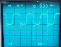
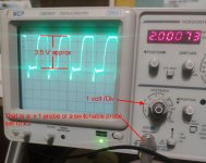
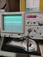
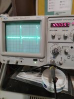
Also, your scope probe looks really badly compensated with far too much overshoot. Can you connect the scope probe onto the probe test point on the scope's front panel, lower left, and take a photo of the square wave that you see there ?

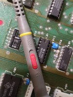
(the probe is behaving as though it has a very high input capacitance, can you state the brand and model number of the probe, I will look it up. I will also conduct an experiment on my PET to see how much added capacitance it takes to upset G5 pin 3. PS...do you have a capacitance meter ?)

Can you advise where you have clipped the scope probe earth clip ?
 
Last edited:
These are some things you could do while waiting for a new 74191:

Possibly the 74191 that you got that is reported bad is ok, and the tester is simply reporting it bad.

Have you checked both the 74191's (the original and the new suspect in the tester ?

and have you tried the new one you have in the PET and checked its Pin 3 output on the scope ?
Hi Hugo...unfortunately I had to throw away the old 191 because I had to cut two pins...I couldn't unsolder them from the board...
 
On the assumption G5 is in an IC socket, you could always bend pin 3 of the 191 out at 90 degrees (so that the pin doesn't go into the IC socket) and test the free pin with the oscilloscope probe.

If it does work then, the problem IS the PCB track on the PET and not the IC...

I would do this simple test first.

Dave
 
Desperado,

I will explain what is going on.

I have attached a photo of the recording from pin 3 G5 in my PET (same board as yours). This was taken with the probe Earth clip onto the negative lead of the large electrolytic capacitor. The probe is a x10 probe. Zero volts is on the center line. And 2v/div vertically(on the display).

The x10 probe has an input capacitance of around 30 to 35pF. Daver2 also mentioned that you should use the x10 probe and I have talked about this too, the Devil is in the detail. I mentioned that a normal TTL output can drive the input capacitance of the x10 probe.

On the other hand, a x1 probe can have an input capacitance as high as 130pF, plus the 10 to 20pF input capacitance of the scope added. To confirm this I measured an assortment of x1 probes I have which came with 20MHz rated scopes.

I applied a variable capacitance to pin 3 of G5 and found that the computer malfunctions when the capacitance is in the order of 120 to 140pF. This overloads the output pin. So it would be normal to get a malfunction if a x1 probe is attached to pin3 of G5. So for this symptom, you/we have been chasing a Red Herring because of the x1 probe.

The effect you are seeing is because you are using a x1 probe (or a dual x1/x10 switched to x1) not suited to the application of testing TTL output pins, as its input capacitance is far too high.And if a malfunction is produced by connecting it somewhere, it is not indicative of a fault there.

I know you are using a x1 probe, or a switchable probe set to x1, because of the Forensic Evidence; your Attenuator switch is set for 1V/division (seen clearly in your photos) and showing TTL logic pulses at about 3.5 to 4 divisions high, typical of TTL. With a x10 probe, to get that amplitude display, your Attenuator would have to be set on 0.1V/div.
 

Attachments

  • G53.jpg
    G53.jpg
    217.9 KB · Views: 5
  • pobe1.jpg
    pobe1.jpg
    144.9 KB · Views: 5
Last edited:
Hugo 'Sherlock' Holden!

Nice work.

@Desperado are you following my instructions or not?

Dave
To Quote you Daver2 from your post #646:

Can I suggest another little test with your oscilloscope?

Set your oscilloscope PROBE to the X10 setting.

We are going to read TTL-level signals - so you will need to set your oscilloscope Y channel to approximately 0.1 V/div - to give 1 V/div actual (you have a X10 probe connected now that will reduce the voltage seen by the oscilloscope by a factor of 10 - so 5.0 V will appear at the oscilloscope as 0.5 V)


but I guess Desperado must have missed those instructions.
 
I am really desperate now....I'm starting to not understand anything anymore....I think this will be my last pet to fix....time to put your hands up :(
 
What are you not understanding?

We think you have not been following my instructions on taking the measurements.

If so, this is not just related to the PET, but basic electronics, use of the oscilloscope to take measurements and the ability to follow instructions.

When you measure anything in life, you disturb it in someway. In this case, the capacitance of the oscilloscope probe is affecting the IC you are measuring to such an extent that it is malfunctioning.

I asked you to set your probe to the X10 setting to take this measurement. It looks like you did not do this.

It is possible that your probe does not have an X1 / X10 switch on it. In this case you are snookered and can't use this probe without upsetting the IC.

Dave
 
Last edited:
>>> I have prove setting to 10X for these measures Dave...

I am not sure what you are saying.

Did you set the probe to X10 or not when you took the measurements?

From Hugo's investigation of your photographs (with the Y knob set to 1 V/div) then it is not possible for the probe to be set to X10 in this case.

What manufacturer and make of probe do you have? Can you post a photograph of any switches and/or controls on it?

Dave
 
This is very interesting... How does it relate to the damp finger test? Does the capacitance of a wet finger make that test unreliable? 140pF sounds like a very small number?
 
This is my probe, maybe i taked measures with 1x button sorry
 

Attachments

  • 1679588778740..jpg
    1679588778740..jpg
    1.5 MB · Views: 4
i am desperate again....i receveid ic spares but 191 is missing...it was ordered later so i will receive it tomorrow or monday.... :(
 
Right, so before you do ANYTHING with the chips make sure you have G5 (191) installed and E11 (165) not installed.

Change the RED switch on your oscilloscope probe to the 10X position (as I asked you to do previously) and set the Y knob on the oscilloscope to 0.1 V/div. Make sure the RED switch engages fully...

Then measure G5 pin 3 again. Hopefully, this time, you should observe and 8 MHz signal and no horrible squeal...

Dave
 
Excellent - perfect. So if we had used the correct measurement setting we wouldn't have all got desperate and a perfectly working 74191 wouldn't have been sacrificed on the alter...

Can you also measure G5 pin 12 (using the same oscilloscope setup) just to put to be that strange reading from last time to bed.

Dave
 
Back
Top