Desperado
Veteran Member
- Joined
- Nov 25, 2017
- Messages
- 6,827
Ok, i replaced UD8 socket...so now what can i do please?Yep,
But be careful of damage to the PCB tracking (especially as it has been replaced before).
Dave
Ok, i replaced UD8 socket...so now what can i do please?Yep,
But be careful of damage to the PCB tracking (especially as it has been replaced before).
Dave
Now i already changed this socket but thanks! I'll keep the advice in mind for next time!I have been over the issue of damaged sockets many times.
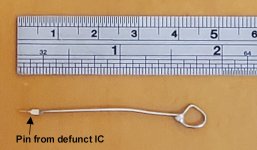
You cannot tell the condition of the socket, in most cases, just by looking. It requires an IC pin on a small wire handle to feel the tension of individual socket claws.
The worst types of sockets are single wipe and the TI sockets that grab the pin from side to side.
The type of socket you have there are normally pretty good, being a dual wipe type. These have an interesting feature, it is possible to replace just one claw at a time, because of the way they were manufactured, the pin comes out of the socket top. So if you are careful you can solder a wire to the claw on the top. The heat the pin on the solder side of the pcb, making sure it is fully melted first, and withdraw just the one claw assembly and replace it with one from a donor socket.
But I would not consider replacing a socket, unless one or more of its claws failed the test for spring tension with the test pin on the wire handle.
Yes Pettester for now is working...Put your PETTESTER ROM back in the new UD8 socket (very carefully...) and set Nivag's ROM links all to OFF (both E and F ROMs if they are not already OFF) and see if that works now with PETTESTER...
Ok thanks Dave, i ll do this tomorrow! Goodnight Sir!Ok,
So switch Nivag's 'E' ROM link to ON (to run the PETTESTER code from Nivag's board) and repeat the PETTESTER test, but for a longer period (say 30 passes).
Dave
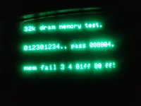
I am desperate! We are at dram step number 30 but the computer does not crash.... what causes the crash then?Ok,
So switch Nivag's 'E' ROM link to ON (to run the PETTESTER code from Nivag's board) and repeat the PETTESTER test, but for a longer period (say 30 passes).
Dave

UD9,8,7 and 6This probably indicates that it is not the DRAM that is at fault but the PETTESTER EPROM or the IC socket that the PETTESTER is sitting in or (more likely) some PCB tracking connected to the UD8 socket.
What ROM sockets have been changed on this board (apart from UD8)?
Dave