fachat
Experienced Member
Hi there,
has anyone actually ever analyzed the static (or even early dynamic PET) video timings? The ones where the video display is created by discrete hardware?
I've been mulling over the schematics for the whole evening, but the use of obscure counters, JK flipflops and strange logic simply eludes me.
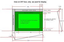
In particular I am looking for how long a rasterline takes, and how many rasterlines there are.
The reason is, in the PET ROM (at least since BASIC 2), there is a small correction in the counting of the Jiffies, in that every 623rd interrupt is skipped and the Jiffy in this interrupt is unchanged. As Jiffies are supposed to be 60 per second, I can only assume that the original PET did not have a real 60Hz display. If I take 60Hz, it would be 16667 cycles per screen - but with a 622/623 correction, this points to 16640 cycles, which is much more likely (e.g. with 64 cycles per rasterline, this would make 260 rasterlines, which would be easy to check for with bit 8 = bit 2 = 1 - if I would even only find something like a rasterline counter .... !
So, if anyone has ever looked at that in detail and is able to share some notes, I'd be very happy!
Many thanks
André
has anyone actually ever analyzed the static (or even early dynamic PET) video timings? The ones where the video display is created by discrete hardware?
I've been mulling over the schematics for the whole evening, but the use of obscure counters, JK flipflops and strange logic simply eludes me.
In particular I am looking for how long a rasterline takes, and how many rasterlines there are.
The reason is, in the PET ROM (at least since BASIC 2), there is a small correction in the counting of the Jiffies, in that every 623rd interrupt is skipped and the Jiffy in this interrupt is unchanged. As Jiffies are supposed to be 60 per second, I can only assume that the original PET did not have a real 60Hz display. If I take 60Hz, it would be 16667 cycles per screen - but with a 622/623 correction, this points to 16640 cycles, which is much more likely (e.g. with 64 cycles per rasterline, this would make 260 rasterlines, which would be easy to check for with bit 8 = bit 2 = 1 - if I would even only find something like a rasterline counter .... !
So, if anyone has ever looked at that in detail and is able to share some notes, I'd be very happy!
Many thanks
André
")