• Please review our updated Terms and Rules here

CRT issue on IBM 5110, working but has some lines after warming up

voidstar78

Veteran Member
Joined
May 25, 2021
Messages
690
Location
Texas
I've transplanted the PSU from my working IBM 5110 Type 2 (no internal tape) over to an IBM 5110 Type 1 (with internal tape).

Everything is working fine (my wife helped with the two ground wires; the stock ones are quite short, and I didn't want to replace/extend them - very glad to have her help)

But I have an issue with the CRT. Thankfully the CRT is working at all, so I'm grateful at least for that.

The CRT is slow to "warm up" -- and that's normal. Things start to become visible when it's about halfway through the startup ROS. Again, that's normal.

Then once it gets to the BASIC prompt, everything looks fine -- nice black background and white text. But then after a few seconds, the screen gets slightly brighter and some lines appear. The lines are not flickery (not like a sync problem), and they're not a side effect of the camera (the curved vertical lines are a side effect of the camera, but not the tilted-horizontal lines that are brighter). It's not a side effect of the brightness knob. In fact, I can turn the brightness all the way down, and the horizontal bright lines stay there.

The lines don't appear on the external BNC connected screen.


screenCRT.jpg


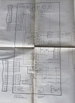
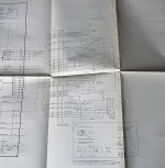
In the IBM 5110 MIM (this same page is basically in the 5100 MIM as well), the CRT that I have is like the lower one in the image.

1652674347125.png


The display centered is OK, character heights look OK. These odd horizontal lines are odd, in that they remain when brightness is lowered, or when using the L32/R32 modes.

If anyone has encountered anything like this and has thoughts on things to try, I'm looking for ideas. Everything else is fine -- tape unit, keyboard, audio bell. The only other issue is there is a slight "clunk" to the PSU fan - it's not as bad as maybe that sounds, I just mean the fan has a noticeable extra sound that the PSU fan on my other 5110 doesn't have. I'll try to get a video later in the week to clarify. But again, they're old components, I'm glad anything works at all :D
 
Last edited:
The lines you are seeing are classical vertical retrace lines. They become visible often when the brightness control is set too high. It looks like it is, or has changed at least, because the background raster scan lines are far too bright. Normally on computer VDU's the brightness control or sub brightness control is set so that the background raster scan and its lines, are invisible (CRT beam is cut off) and only the characters/graphics are illuminating the screen phosphor.

Since it starts off ok, then it changes, and the brightness ramps up, illuminating the raster scan and the vertical retrace lines, then some intermittent fault is affecting either:

The CRT's cathode voltage....or

The CRT's grid (g1) voltage.

This is because the CRT's beam intensity is controlled by the relative grid to cathode voltage of the CRT's gun.

For example, if the grid to cathode voltage is zero volts, the CRT's beam current is maximum. It normally takes a voltage negative on the grid, with respect to the cathode, of around 50 to 60V to extinguish the beam.

Generally, most VDU's have the video signal introduced to the cathode, and the brightness control Pot introduced at the grid. But there are many variations to achieve the same result.

If you could find the schematic for this VDU I could suggest what to check.

If you look you will see there are two brightness potentiometers. One is on the front panel for the user to manipulate, the other in the image you posed, is on the pcb, that is a sub brightness control, to set the operating range of the front panel user control. Exercise both of these with some contact cleaner and check the connections from the external brightness control to the pcb as a start.
 
I've never found a proper component-level schematic of the 5110 equipment. We do have the Logic Manual, that describes some aspects of signal flow (attached). The ones for the Display are attached (I assume the stuff about "World Trade" is maybe special character support when connected with the optional comms components, the "Katana" stuff).

The front panel Brightness control does reduce/increase the overall brightness and character text, but IIRC had no impact to the brighter horizontal lines. (i.e. if turned the Brightness down such that the character text is barely visible, and yet the few prominent horizontal lines remain visible).

And thanks, can try the contact cleaner this weekend.
 

Attachments

  • IMG_1882A.jpg
    IMG_1882A.jpg
    359.3 KB · Views: 5
  • IMG_1883A.jpg
    IMG_1883A.jpg
    300.1 KB · Views: 5
I wonder if the 5110 Logic Manual contains similar information to the Circuits portion of the IBM 5100 Maintenance Information Manual. PDF pages 286, 287, and 295 in that book seems to show similar information to what's visible in those photos.

But it could also be that what you need to know is information that's beyond the "CRT Connector".

PDF page 56 has a drawing of the VDU but nothing that will be especially helpful here.
 
Last edited:
I've never found a proper component-level schematic of the 5110 equipment. We do have the Logic Manual, that describes some aspects of signal flow (attached). The ones for the Display are attached (I assume the stuff about "World Trade" is maybe special character support when connected with the optional comms components, the "Katana" stuff).

The front panel Brightness control does reduce/increase the overall brightness and character text, but IIRC had no impact to the brighter horizontal lines. (i.e. if turned the Brightness down such that the character text is barely visible, and yet the few prominent horizontal lines remain visible).

And thanks, can try the contact cleaner this weekend.
You need to adjust the internal brightness control (aka sub-brightness).
 
(i.e. if turned the Brightness down such that the character text is barely visible, and yet the few prominent horizontal lines remain visible).

And thanks, can try the contact cleaner this weekend.

That is suspicious of a VDU fault. In many VDU's a pulse is taken from the vertical scan output stage, differentiated by a C-R network, and coupled to the CRT (typically it is a negative going pulse coupled to the grid, but sometimes its a positive going one coupled to the cathode). This is the vertical retrace blanking circuit, the circuit is to extinguish the vertical retrace lines. This helps avoid the retrace lines being seen regardless of the brightness and contrast control settings.

Some small monitors (VDU's) though, did not have this "Internal retrace blanking" pulse. In this case it relies on three things not to see the retrace lines.

1) the contrast control is set properly
2) the brightness control is set properly
(These first two make sure that the black level of the video signal corresponds to the CRT's beam just being extinguished)
3) the video signal is normal both at the input to the VDU and after it is amplified to drive the CRT (Typically its cathode)

If the video signal is abnormal then, in the vertical blanking period (around the vertical sync pulse) and say the level too high, it will brighten up the CRT beam and and allow the vertical retrace lines to be seen. So the first step would be to check the video input signal and then also check it after amplification at the CRT, with the scope.
 
.........also regardless of the level of contrast (vide signal amplitude) is should be possible to extinguish the beam completely (including retrace lines) if both the brightness and sub-brightness controls are correct, so again, check their wiring and give them a clean.

I have some schematics of small VDU's like this, they won't exactly match as they are a different manufacturer, likely, but they could give you an idea of the general architecture of these small VDU's. I'll look for it tonight.
 
It's fixed :D

I turned the sub-brightness (marked "BRT" on the CRT PCB) counter-clockwise about 1/4 turn (total guess).

It was exciting to stick a metal screwdriver down into a thing labeled "CAUTION ... 9KV"

In hindsight, a plastic spade would have been better. (fwiw, the AC power cable had been unplugged for over 24 hours)

Worked like a charm! The screen remained solid black background for many minutes before I powered back down. (the white font text still looks fine, front panel brightness control works fine -- the extra horizontal lines are gone, as well as the slight overall brightness in the background)

Thanks for the confidence to give it a try!

IMG_1885B_small.jpg
 
Last edited:
It does raise the question why the sub brightness control setting was incorrect, possibilities:

1) somebody before you tampered with it.

2) there was a bad connection of the wiper to the carbon track that cleared when you rotated it.

3) one of the filter capacitors in the circuit associated with the sub brightness pot has become leaky , requiring a different adjustment to what was formerly correct.

The 9kV is of no worry as it is fully insulated, so you don't have to be concerned unless you go under the CRT's grey anode cap. Which you don't need to for most CRT servicing. If you go under there leave it a day for the CRT's bulb capacitance to self discharge via the non-zero leakage on the EHT rectifier and obviously only go under there, if you had to, while it is switched off. Even if you went under that anode cap right away after turn off, the amount or stored energy there is harmless, well under 50mJ, unless it gave you a fright, it would feel like a single zap from something like a lawnmower's spark plug, which has a similar energy.
 
Last edited:
Back
Top