• Please review our updated Terms and Rules here

Disks not reading after lubricating 1541 spindle hub

powerlot

Experienced Member
Joined
Nov 20, 2021
Messages
483
Location
Europe
Hi vcfed community

I have a Commodore 1541 disk drive with an Alps mechanism FDM2111-B2 that was dirty and loud, but in working condition.

To learn a bit about the drive and tinker with it I decided to follow some YouTube videos: swap out the power supply and clean / re-lubricate it.

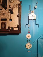
It all went well up to the part where I dropped some liquid lubricant onto the c-clip of the spindle hub. Then the drive started to not read disks reliably and when I took it apart it all went downhill, as the washers and springs spilled all over the place.

I tried different arrangements of washers and varying amounts of silicon grease (of the non liquid kind) but without success, no matter what I do no data is ever being read. The diagnostic cartridge program reads track 1 on all tracks and the speed adjustment reports an error. The speed seems OK when looking at the strobe wheel and I haven't had any obvious issues with the logic board.

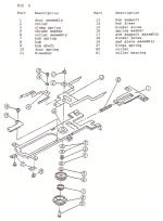
Since all the parts went flying when I took it apart I'm not 100% sure I've got all of them. According to the service manual (fig9) there should be two washers between the spring and the clamp, but according to here (https://www.lemon64.com/forum/viewtopic.php?p=847809&sid=f29d41edb425d23977e7f006c33c8d87#847809) it can vary between drives.

Without a second one to verify and my lack of experience of these drives I cannot fix it anymore and am therefore asking for your help.
Could someone verify that I've got all parts (see attachment) and how I could rule out problems other than the disk not spinning correctly?

Thanks for your support.
 

Attachments

  • 20220130_182150-2.jpg
    20220130_182150-2.jpg
    136.4 KB · Views: 36
  • fig9.PNG
    fig9.PNG
    211.6 KB · Views: 35
Looks correct to me.

Have you checked the resistances of the r/w heads? It's uncommon for Alps heads to fail but certainly worth doing.

Also, it may be that some of the circuitry has become inadvertently damaged, UC1 plays a big part in controlling the movement of the stepper motor (as does UC2, one of the VIA's) it's not impossible that they've failed through static discharge - I've fallen victim to this myself.

Another failure mode I've seen is not having the metal 'prongs' of part 13 in the diagram tucked _under_ the top of the brown plastic front fascia, a drive I received had these above which prevented the upper mechanism from being able to press the disk media against the r/w head.

I realise you posted this a few weeks back, but I hope this helps.
 
Hi and many thanks for confirming that the order of spindle parts looks ok.

The r/w head wires have a couple of Ohms of resistance between them and none seem broken, if I understood right this is how it is supposed to be?

How can I measure if UC1, UC2 or the heads are behaving correctly? The movements seem alright.

I'm going to check for incorrect assembly of part 13 and I'm probably also going to procure another 1541 to have a working sample.
 
Resistances should be as per the service manual: https://www.classic-computing.org/wp-content/uploads/2016/01/15401541_SERVICE-MANUAL.pdf

Extract here:

checks.jpg

There's a reasonable troubleshooting guide in there, but I tend to use Ray Carlson's chip fault finding guide from here : https://cbm8bit.com/articles/ray-charlsen/article23

Check that your mechanism looks like this (ignore the gunk/foil, I had to repair a snapped latch), of importance is that the thin front 'arms' of part 13 from the exploded diagram in your original post are UNDER the top bezel of the front plate, if this is not the case you will have no pressure holding the disk media against the r/w head.

PXL_20220225_100526102.jpg

Specific testing of UC1-UC3 is a little tougher, I've not found a definitive guide on what signals to expect on what pins - by following the board schematics you can work out where you should see signals with a logic probe/scope, but it's laborious work. Most people diagnose through chip substitution.

Use an earth strap! And never hot plug anything.
 
Well, here's the results:

The resistances all seemed alright except for the spindle motor which had double the motor coil and slightly higher tach coil resistance. The erase head coil one was also a bit higher.

I tested the drive on a working board at it's flawless, which means the problem is indeed on the logic board or power supply :/

I'll revert the psu mod and hope that unclean power supply was the issue, else I'll have to troubleshoot the board.

PS.: I'm using the strap from now on
 
I changed it back to the original power supply and the fault remained, also after swapping UC2+UC3 (at least those are fine).

There's a reasonable troubleshooting guide in there, but I tend to use Ray Carlson's chip fault finding guide from here : https://cbm8bit.com/articles/ray-charlsen/article23

Any tips on how do I check these? Just probe them and look for unusual signals? The drive controls seem ok, just getting FILE NOT FOUND or READ ERROR
UA1 74LS14 LOGIC
Partial failure common cause of "FILE NOT FOUND" error. Total
failure: when drive powered up, red LED stays on and spindle motor
runs continuously (check also UB4, UC2, UC4, UC6, UC7, UD3, and UD5).
UE4 LM311 COMPARITOR (READ)
Drive powers up and resets normally. Spindle motor runs, stepper
moves slightly, but "FILE NOT FOUND" error, and red LED flashes.
Check also UF3 and UF4.
UF3 NE592N (LM592) READ PREAMP
Drive powers up and resets normally. Spindle motor runs, stepper
moves slightly, but "FILE NOT FOUND" error and red LED flashes. Check
also UF4 and UE4.
UF4 NE592N READ AMPLIFIER

Powers up normally. When LOAD attempted, spindle runs and red LED
comes on, but "FILE NOT FOUND" and red LED flashes. Check also UE4
and UF3.
 
You could work outward from UC1, there's a data in pin where a serial stream comes in from the read head, it's get's differentially amplified by the 2 592's and then more so by the 311. UC1 then essentially deserialises the data stream and pops it out 8 bits at a time to UC2.

I'm not sure which board you have, but with it being Alps mechanism I'd guess it to be 1540050, 250442/250446, you can track the signal paths by pin on there and hopefully then by process of elimination figure out exactly what's at fault.

I just had one with the exact same symptoms and one of the 592's had failed. A previous one had a failed UC1. I don't recall the signal levels that should be expected there, but I could probably break out the scope and check on a working drive against anything you observe.
 
I have a working 1541 with 250442 board and the one that I'm troubleshooting is a 250446.

Test setup: Ran the diagnostics cart track alignment on loop with a demo disk.

Here are my test results, something is faulty, but I wouldn't know which part.

UC1:
Pin 22: On the working it looked like data being read, on the broken one it was like this:
DS1Z_QuickPrint28.png

UE4
PINUE4 working driveUE4 broken drive
10V0V
2DS1Z_QuickPrint23.pngSteady 5,8V
3DS1Z_QuickPrint24.pngSteady 5,8V
40V0V
512V11,7V
612V11,7V
7DS1Z_QuickPrint25.pngDS1Z_QuickPrint29.png
812V11,8V

UF3
PINUF3 working driveUF3 broken drive
16,8V3,8V
20V0V
36V2,6V
46V2,6V
50V0V
60V0V
79,8V11V
89,8V7V
90V0V
1012,5V11,8V
116V2,6V
126V2,6V
130V0V
146,6V0,8V

UF4
PINUF4 working driveUF4 broken drive
16,4V5,8V
20V0V
35,6V5V
45,6V5,2V
50V0V
60V0V
7DS1Z_QuickPrint26.png nothing / fuzzy line
8DS1Z_QuickPrint27.pngnothing / fuzzy line
90V0V
1012V11,8V
115,6V5,2V
125,6V5,2V
130V0V
146,2V5,8V

Any ideas? Could it be UF3?
 
Good news! After checking the transistors and diodes up to UF3 and finding nothing out of place I replaced UF3 and it fixed the problem.

The drive runs quiet and smooth now and reads disks like a charm!

Thanks BennehBoy :biggrin::biggrin::biggrin:
 
Hi!
I have an ALPS 1540050 drive with one last gremlin: the same «all tracks reported as 1» and no RPM detected error.
This drive has had a catastrophic failure on the 5V rail, so a ton of chips got toasted.
The drive is now in a technically and mechanically (verified with another board) working state, except no data is actually decoded.
It is worth mentioning that there is no head knock during boot on this drive, and that the «down clocking» during the upper tracks seem a tiny bit off when compared with the service diags.
Also, when I first opened the drive for inspection, the head connector was inserted in reverse.

Before I order some new NE592, I would like to hear other opinions, as these chips do actually output, but a bit lower than mentioned here.
The board has been «worked» on previously by some other «techs» and had multiple torn traces arround UC6.
I’ve repaired them all according to the 1540048 schematics, but I saw a close up of a similar board that had factory cut traces around that section.
The decoding of data shouldn’t be anywhere that chip, yes?
 
Hi, if I understood correctly it needs to amplify enough to be decoded as proper highs and lows by the 311 (UE4).. check posts 7 + 8.. what does pin 22 on UC1 look like in your case? Subsequently, what's going in and out of UE4?

If you suspect faulty heads, go to post #4 and check the resistances.. you can start from either side and work your way through
Thanks for replying!
I can confirm working mechanics/head as it is working as expected with another mainboard.

According to my memory, uc1 pin 22 looks quite the same as the image previously posted: continuous pulsing.
Meaning no data decoded?
I’ll verify this later.

It is worth mentioning that the dm9602 was shot, so it was replaced with a «genuine» asian chip. It looks like it is doing it’s job though.
I also have a real 74ls123 at hand which I could rewire in there if suspected.

I’ve installed a brand new lm311, no change.

The thing is that the output of lm311 and ne592s look like there is data there, but possibly too low in level to decode.

I could swap the ne592s from the working drive, but it is the most un-socketed board I’ve seen. It is in very good condition and I don’t want to rip traces.
 
Last edited:
Thanks for replying!
I can confirm working mechanics/head as it is working as expected with another mainboard.

According to my memory, uc1 pin 22 looks quite the same as the image previously posted: continuous pulsing.
Meaning no data decoded?
I’ll verify this later.
In my case, continuous pulses were on the broken drive (as in the picture from the previous post). The good drive had activity ("random" highs and lows).

It is worth mentioning that the dm9602 was shot, so it was replaced with a «genuine» asian chip. It looks like it is doing it’s job though.
I also have a real 74ls123 at hand which I could rewire in there if suspected.

I’ve installed a brand new lm311, no change.

The thing is that the output of lm311 and ne592s look like there is data there, but possibly too low in level to decode.

I could swap the ne592s from the working drive, but it is the most un-socketed board I’ve seen. It is in very good condition and I don’t want to rip traces.
I would measure the NE592s again. You can see in post #8 that the voltages weren't near where they should have been compared to the working drive
 
Well, I just went ahead and desoldered the ne592s from the functional drive.
No change, and I verified the pair from the non-working drive actally did it’s job.
Now things got a bit more complicated.

No obvious resistors, diodes or trannies differences in the r/w section found between them.
Also, UC1 is once again verified as doing it’s job.

Now, how I understand it is that if any ports on UC5, 6 and 7 fail, the drive will redlight fail?
Since there was a ton of traces there destroyed by previous «techs».

Curiously enough, I noticed in a repair video on youtube where two traces was factory cut on the left side of UC6.
On my board, these cuts correspond with UC6 pin 2 and UC5 pin 12, which actually seems to make some sense, as it separates a condition on the gate?
The other cut would be UC7 pin 14 and UC4 pin 20, which is A11 so it wouldn’t make much sence here?
 
Ok, it's a tough one... Unfortunately I don't know these drives well enough to make qualified suggestion... so here some guesses:

Do you get the wavy signals on UE3, UF4 etc. when there is reading going on, and something on the data in pin?
You could work outward from UC1, there's a data in pin where a serial stream comes in from the read head, it's get's differentially amplified by the 2 592's and then more so by the 311. UC1 then essentially deserialises the data stream and pops it out 8 bits at a time to UC2.

Is it obvious which changes are from factory and which from the previous "techs"? If there was a failure on the voltage rails, it could be that one or more logic chips got damaged and you'd probably need to test them as well. Have you compared the signals going through UC5, UC6 with your working board?
 
I just saw my hiroshima 1541 read, write and format again!
The sinner was as I previously suspected: The very «genuine» UD4 DM9602 i bought from Asia.
The failure was not generating sync pulses timed correctly
I swapped it for one of the other 5 chips from the same bundle.
All is good now after two years of investigation, and a body count I’ve lost track of.
What a ride!
 
Back
Top