NTICompass
Member
I recently acquired a Faraday A-Tease 286 motherboard. It seems to have onboard RAM and uses an Intel C80286-6.
I am having trouble finding a manual or any info on this board.
Specifically, what PSU (or adapter) do I need to power this board up? I have an AT/XT PSU with P8/P9 connectors, but that doesn't seem to be correct. I suppose I should also figure out what each of the jumpers do, too.
Also, are the ROMs for this board available somewhere, or should I dump the ROMs and upload them?
Here are some pictures: https://photos.app.goo.gl/aaGMYBJk7EqqXQNh6
I posted this on Reddit ( ) and while waiting for a reply, I did some research.
I've found reference to this board (its POST codes) here: http://minuszerodegrees.net/manuals/Ultra-X/Ultra-X - R.A.C.E.R. II - Users Guide.pdf (page 8-21).
Another POST code page says "Faraday A-Tease: Owned by Western Digital": https://mrbios.com/techsupport/award/postcodes.htm
I found the jumper settings! Apparently, this board is by Western Digital. http://vtda.org/books/Computing/The A+ Reference Book - Phil Croucher - 2000.pdf (Page 579).
You know, I didn't take a picture of it, but this board did come in a Western Digital box. I figured that was just a random box, and not its original box.
A reddit user helpfully posted a catalogue mentioning this board: http://www.bitsavers.org/components/faraday/1986_Faraday_OEM_Catalog.pdf (page 61).
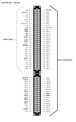
It mentions the PSU connector and MOLEX part numbers:
Seems like those are just the housings/pins for the cable. So, I could make the connector, and put some wires in it... but I'll still need to determine the pinout.
So, yeah, has anyone seen this board or a similar one? How can I determine the PSU pinout and power this board up?

