• Please review our updated Terms and Rules here

IBM 5154 EGA monitor fried... is it a goner ?

It took about three weeks for spares to arrive this time. Slow... domestic order too.
But I'm back with troubleshooting the EGA monitor.

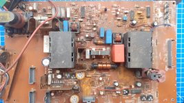
So, I ended up replacing T400, T401 and electrolytic cap C256, because it looked to me
like there were tinyist bulging going on. ESR meter however did not show that cap at fault.
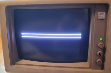
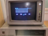
I tested the monitor (picture 1) and now the image on the screen fits nicely horizontally !
Result there, I suspect just replacing the shorted transistor T400 maybe would have been sufficient.

Next, there were still the nasty foldover issue. Plus, the image would bounce very easily up and down again.
I was hoping the bouncing issue would be solved at the same time with the foldover issue.

So, SAMS manual suggests to check diodes D301, D302 and D303. They were all good.
Also, recommends to check caps C311 and C312. I had already replaced C312 earlier,
so I replaced C311 with 100uF /63V low esr cap (since 100uF/40V is not available).

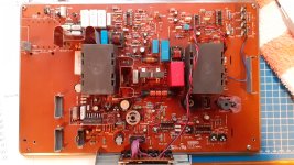
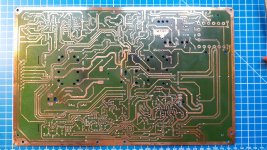
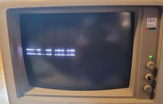
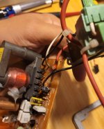
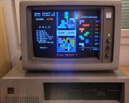
Doh, picture 2 shows the result when computer starts. Picture 3 is when pc is powered off.
Oh well, one step forward, one back. I checked that all cables are

The old removed C311 shows 118uF value and about 1ohm resistance with my esr meter.
I will check voltages from IC300 next and probably, I will put that old C311 back just to see
if it works better than the new replacement I put there.
 

Attachments

  • 1.jpg
    1.jpg
    175.9 KB · Views: 14
  • 3.jpg
    3.jpg
    136.8 KB · Views: 15
  • 2.jpg
    2.jpg
    204.1 KB · Views: 15
Okay...

IC300
voltage at pin (and what it should have):
1) 6,8v (7.3V)
3) 3,0v (2.4V)
5) 21v (20.4V)
7) 0.6v (11.? )
9) 21.7v (21.0 V)
11) 2.9 V
13) 4.1 V (4.4V)

Right, pin7 has 0.7V and it should have around 11V. That pin is also directly connected
to the C311 (and C312) that I have replaced. A bad cap? I did make sure to put negative leg to
where it is supposed to be.

Taking the C311 out again...
 
Did you replace all the electrolytic capacitors in the power supply ? The power supply in the 5154 runs
very hot due to the metal enclosure, and the caps are only rated at 85 C. It's a good idea to replace them
all with 105 C rated caps.
 
Thanks for your input, Mikey99.

Short answer, no. In fact, I have not replace any of the psu caps.
At the moment, I'm trying to solve issue about vertical display.

I put the original C311 back (since my new replacement seemed to collapse vertical display).
To my surprise, this had no effect at all. The display looks like my latest post image 2 (if pc is powered on)
or image 3 (pc powered off).

I double checked I have all the cables plugged in. Pin 7 of IC300 still has about 1.2V and it should
have 11V, so I'm assuming the issue is related to this.

My theory is, that either it is not supplied sufficient voltage or the IC300 itself has failed.
What ever it is, it seems like it went worse from before, from fold over issue to this. I'm
debating myself weather I should order IC300 (TDA2653A) or keep replacing components that are
related to pin 7 of that chip. That IC is a bit expensive and it's going to take a few weeks again to order
from somewhere in EU. I don't think I will find it domestically in Finland.

Any more educated suggestion is appreciated. But, I will keep at this eventhough it is slow work.
 
That's a great idea, Chuck!

Pulled leg7 of IC300. pcb has still 1.2V -> therefore the issue is likely elsewhere and
not in IC300!

Good - I'm not spending 3 weeks waiting for that IC, but will try to find out where else
the issue lies.
 
Hey!

Where is that red wire from voltage multiplier supposed to be going?
I assume to the 8000V transformer, probably to inside that black insulator
coming from inside that silicon blob ?
 

Attachments

  • red_wire.jpg
    red_wire.jpg
    250.5 KB · Views: 14
Yeah,
it must have come loose at my latest fiddling with the main board. I connected it back to the transformer,
where it got loose and I was back to the last pic that I posted: vertically collapsed image.

I have substituted IC501 and IC505 with new ones (they are related to vertical sync), but no change there.
In the end, IC300 is still one suspect so I ordered one from Spain. Let's see how long that takes to arrive.

edit:
I noticed there is another anomaly with voltages for IC300. Pin2 = 17V (should be 0.1V).
The first one we discussed earlier was pin7, that has about 1V (it should have 11V).

edit II:
If I pull video board out of the main board and then power up the monitor,
pin 7 of IC300 actually rises to 7,6Volts. Pin2 remains at 17V.

Not sure if I can draw conclusion on this, but it would seem something at videoboard
draws IC300 pin7 to gnd.
 
Last edited:
Forgive me for barging into this thread with a tangentially related matter, but I've recently acquired a second 5154 that will work perfectly at 15kHz but will not sync to 22kHz. This is tested on an original IBM EGA which works flawlessly with my other 5154, so I know the sync polarities are correct. Any ideas where to start looking?
 
I hope you'll find solution to your problem maxtherabbit. I have no idea what to do with that.

I received IC300 (new oldstock) replacement yesterday. Put it into the main board, but I had no change
to my issue there. I was betting that IC was a good candidate for the problem, but no.

Oh well. So close, yet so far that it is tiny bit frustrating.
 
Okay, after nearly a couple of weeks I got back to the EGA monitor.
Measured voltages again from IC300. Inspected the pcb and suddenly I noticed that
there is a problem with C304. A cap that I had replaced some time ago had ripped its legs off
the contacts from the pcboard. That needed to be corrected of course.

I assumed and hoped that I'm back at the foldover problem after this fix, but what !
Not only that, but the fold-over problem is gone as well !! WOW - I did not expect to see this much
improvement!

I have to assume that replacing the IC300 earlier fixed the foldover issue, because it was there
with original C304.

I'm very exited, but also hoping that nothing else fails on this now. It's been two and half months
working on this and I'd like to finally, finally put it back together.
 

Attachments

  • works.jpg
    works.jpg
    126.7 KB · Views: 15
I assembled the psu and video board in their metal casings.
Assembled the monitor. Now when I turn it on, the screen remains white,
even when connected to the pc.

This thing is really fighting me. Just when you think you're done, you can start
to think otherwise.
 
At long last... there is a picture on the screen when I have assembled the unit!
This is the time I've been waiting for... for 3 months now. I won't call it ready yet,
until it proves to be working for some time. Also, looks like some CGA graphic mode is
shrinked too small. I need to test this a bit further to see if it really is ok.

The last white screen issue was bad solder connection on one of the IC's that I had removed.
I put IC socket in it's place but it had bad solder joint. Now that I found out and fixed the problem, I have
picture.

I wish I could say it was a pleasure to fix or great project, but it was a pain instead. Still, I'm very glad
there is again image on the screen!

Maybe a short summary of what was wrong with the monitor for a reference if someone is trying to fix one of these:

Two bad filter caps at psu (C7 and C6 if I remember correctly).
Symptoms: Immediate expolosion, electrical fire soundeffects and thick white smoke after connecting
the unit to power cord =).

Bad 12V regulator at psu (IC2, 7812CT)
Symptoms: 12V leg of regulator showed 0 V. No 12V, no 5V, no green power on LED, no raster, screen remains black.

Shorted power transistor T400 (TIP308, main board)
Symptoms: Collector voltage wrong - Emitter+Collector shorted when transistor pulled from pcb. Image width is oversized, image cannot fit the screen. Adjusting image width with rt401 or rt402 (horizontal width controls) will not be able to shrink image width sufficiently.

Faulty IC300 (TDA2653A, main board)
Symptom: Vertical image foldover problem. Probably also causing vertical shaking of the image.

Bad contact for C304 (C304 out of pcb). My own mistake, but blown C304 might cause same issue.
Symptom: Image collapsed vertically (into one or two lines)

White screen issue was caused by my own mistake as mentioned above. One leg of IC501 had bad contact.

If an admin would like to add *Solved* to the topic, feel free to do so =). Something else will probably fail
anyway, but I can continue the topic if I can solve the next issue!
 

Attachments

  • two.jpg
    two.jpg
    156 KB · Views: 22
  • one.jpg
    one.jpg
    207.7 KB · Views: 20
Last edited:
Hi VintageVic,

Thank you for the breakdown and the updates on what problems you encountered. It is very useful to people trying to get these old monitors going again.
I am trying to revive an 5154 that I've picked up, but it looks like an uphill battle. The poor thing appears to have had multiple attempted repairs in the past, and in some places the traces have been lifted and broken completely off the main board.
The power supply has now been mostly rebuilt and seems to be working. :)
When you were taking photographs of you monitor PCBs, did you happen to get shots of the top and bottom of the main board?
I have the Sam's document, but the images are very difficult to make out. If anyone has some good photos of an undamaged (or less damaged) example, it would be extremely helpful as I try to rebuild mine.
Fortunately the ICs all appear to be in place, in addition to the rarer transistors.

Thanks again!

-Dominic
 
Hi irrationalforest,

and welcome to the forum!

I was hoping this thread to help someone later. Checked what images I had in my hard drive and seems that I mostly
pictured psu and video boards, but not the main board. Give me a few days time and I could open up the case and take
a photo of the main board underside. I'd rather not pull out the board off the chassis though if not really necessary.

It's nasty trying to fix something that others have tampered with before. Even fixing my own mistakes were
difficult to spot. The traces in these monitors are really easy to destroy as well.

Perhaps you could PM me your email. Posting images here are very low res due to size limitation. I can email
better quality picture for you.
 
Hi VintageVic,

Thank you so much for replying, and for the warm welcome!

Yes, you're absolutely right - it is an extra layer of challenge trying to sort out something that has been worked on by others unsuccessfully.
These monitors are so rare that I would like to repair it, even though the project is a difficult one.
The photos you've posted in this thread have already been very helpful with the power supply. Much appreciated.

I'd be really grateful for any photographs you could take of the main board specifically, if you get time. The desire to keep it in the chassis is completely understandable, especially as these things are pretty easy to damage. Whatever you can get without taking it all apart will be great. :)
I'm just trying to get an accurate picture of where traces and components went before the components were removed and traces lifted.

Unfortunately I can't PM you, as I'm a new member and I think it restricts PMs. Sorry!
My email address is IrrationalForest at gmail dot com, if that works?

Have a great Thursday/Friday!
 
Last year I restored a water damged IBM 5154002 (european/german):

20211223_112257.jpg
to this (about 80% new parts):

20220214_170443.jpg

I had to do some work on the PSU (obligatory recapping of the rifa and smaller elkos) as well as the video board. The monitor is working again, however the picture is dim and when I turn the brightness and contrast nobs the picture shifts and resizes as well. There are several potentiometers that I probably have to adjusted to get a better picture. Nevertheless, after desoldering the whole mainboard and replacing most components I was suprized that it did turn on after all.

Here is a picture of the traces on the mainboard after polishing the copper traces and before adding solder and new PCB paint:

20211230_104610.jpg


Btw, I noticed some differences between SAMS photofact and the values of caps, and resistors found on my board. Furthermore, some of the smaller transistors did not fit the footprint on the board, so take care with emitter, collector and base, and where also different from those named in SAMS.
 

Attachments

  • 20211223_112257.jpg
    20211223_112257.jpg
    2.8 MB · Views: 11
  • 20220214_170443.jpg
    20220214_170443.jpg
    2.8 MB · Views: 10
  • 20211230_104610.jpg
    20211230_104610.jpg
    3 MB · Views: 14
Back
Top