• Please review our updated Terms and Rules here

IMSAI PCS-80/35 or maybe an IMSAI 4x

AlbertS80

Member
Joined
Mar 4, 2022
Messages
27
I have an IMSAI PCS-80/35 or possibly IMSAI PCS-4x system that I was asked to review for a local non-profit.
My time is just for a favor for a place that helps provide low cost working computers and proper recycling of others that are out of date.
I have downloaded numerous IMSAI docs that I can find, though most are scanned and not searchable.
I'm sorry, I have not read these all end to end, so I may be a bit unformed.
I have gone through full dismantle and reforming power supply caps so I believe they are acceptable; less than 1 ma leakage.
DC voltages out of the supply seem correct:
CurrentVoltageLoad ResistancePRipple Vp-pNotes
7.857.85161.62250.3Sawtoothish
1.5415.41023.7160.68Sawtooth
-1.70106-15.999.427.200010.8Sawtooth
I have checked all PCAs, VIO-D, MPU-D, RAM-16 (2x), RAM-32, PDS and DIO.
I measured DC in for all voltages, DC out from the regulators, and the only one I am nervous about is on the DIO with 39 ohms on the load of the LM7805; it may be OK.
The gold fingers were wiped with Deoxit gold stuff.
Same with the EXP-10 main card.
..
This unit came with 2x internal Shugart SA-400 , no internal or external monitor, but I also received an external cabinet with 2x Shugart SA-800 and PS (not really relevant to my questions).
.
I received a NEC JB-1201M (A) monitor which I connected to the VIO-D (slot 2) with the MPU-D (slot 4) card I get output to the monitor.
It is a bit gibberish, but seems to look like "SPACE BAR".
Pressing the return key I see:
IMSAI MPU-B Monitor VERS 1.3
Looks good so far!
.
This came to me without the IKB-1, but what seems to be a parallel port keyboard from Maxi-Switch.co.
There is a sticker on the keyboard from 1982, so it was was made after the IMSAI.
The p/n of the keyboard is 2160055 on a label on the keyboard that is almost falling off.
With the keyboard it seems like I get automatic spaces after some characters entered.
As example when I press "T" on the keyboard I get a space automatically added.
I'm not sure if this is the MPU-B "bios" of a fluke of the keyboard.
Maybe someone can comment on this and help me if this to be expected, or if I need to try to source an IKB-1.
....
Another issue is if I try the "BIOS" diagnostics with one of my three memory cards in slot 9 (one at a time):
T @
I always get the response
0000 FF 00
...
Any speculations if I have three bad memory cards, or some OE (operator error) on my part;
or if this is an artifact of the keyboard that I have.
.
Any suggestions would be appreciated.
.
Thanks - Al
 
Well it seems like I am making a little progress. It seems now that I can test the MPU-B RAM and VIO RAM successfully. Maybe this was a syntax OE error on my part.
It seems like I can display MPU-B ROM.
Wish there were a way to test the RAM-16 or RAM-32 cards in monitor.
I put in the 2x RAM-16, 1x RAM-32, the PSA and DIO card.
When I press B in the IMSAI monitor I get:
DISK-ERR- FF
I have a DIO/PDS disc controller for the system. The DIO card had a 39 ohm reading on on the 7505 output (+5.0); most other cards were around 200 ohms. Anyone know if this is suspicious? I have an extender card and the 7505 output on the DIO is like +4.96 or so.
..
My son has a means to test the Shugart SA-400s tomorrow; use the divide and conquer process.
..
Any thoughts on the DIO ohm reading appreciated.
..
TIA - Al
 
My son dropped off a 486 computer with an older disk controller today.
It does not seem to work with the Shugart - or more OE on my part.
I am looking at a video on youtube:
that seems up the alley.
Also found this which may have been referenced in the above video:
I'm going to keep plugging along.
 
I am still using my sons Asus 486 PC to play with this.
What I found out today was the Shugart SA-400 floppy interface differs from the current floppy interface.
The Shugart SA-400 used pins a bit differently than current floppy designs.
The Shugart supported 3 drive selects, but only only 1 motor on .
With the Shugart interface if you have more than 1 drive and you want to access them all drive motors will all be on; there is only 1 motor on signal.
The current floppy interface allows for either drive 1 or 2 to have their motor on.
To accommodate this the current interface changed Shugart drive select 1 became legacy floppy drive motor on 1
(all of this is 1 based indexing, I didn't use 0s so 1 is the lowest drive n is higher).
So to plug this drive into a normal PC there are a couple of problems:
Shugart drive select 1 is current "PC" motor 1 on and Shugart drive select 3 is legacy drive select 1.
The convergence is with Shugart motor on (pin 16) which becomes legacy drive 2 on
and for Shugart drive select 2 which maps to legacy drive select 2.
The Shugart drives have a drive strapping option for drive 1,2 or 3; I set my drive to 2 and then in the bios selected drive a to be drive "B".
I can now access the drive, but I am bumping on some issues with:
35 tracks, 18 sectors and 125 kHz reading / recording rates.
With the drive installed and using IMD v 118: http://dunfield.classiccmp.org/img/index.htm
Running IMD from a DOS prompt
Usings the (S)ettings option I was able to set the drive to:
B drive,
35 cylinders
single head
double step to off
The short coming was I was only able to get 250 kHz as the lowest setting read setting, and no sector count.
With the (A)llignment option I can confirm that the stepper motor seems to be working using the Z commands to set the drive the 0 cylinder
and then pressing 0-34 to step the select motor.
I had a scope on the track 0 test point and could see it switch off which gave me confidence I was doing something when I changed from 0 to something else and returned to 0.
I found this document on the Shugart SA-400 that was maybe
This is pretty sweet. It has much more detail than I have found before.
This is the start page in Archive.org:
This is where I got the test test point info.
I'm pretty sure many others have found this stuff before.
I think you may think I am a slow fool.
I have looked at the read data test point and it seems like data is coming off the disk
I am beginning to think my drives are OK and maybe I have a DIO/PDS issue.
I may get back to that tomorrow.
I'll keep plugging
 
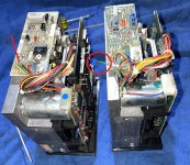
I neglected to note that my drive 2 was spinning fast. That was due to a broken wire on the drive 2 motor.
The motor was spinning too fast. The wire appeared attached, but when I moved it slightly I could tell it was broke:
IMG_0015b.JPG
Today I scrapped (removed) the disk subsystem (DIO/PDS) and decided to focus on the memory cards, 2x RAM-16 and 1x RAM-32.
This was a positive note.
All three cards ran the BIOS test (BIOS is known as "monitor" in IMSAI land, at lest for the PSC / MPU-B land)
The only thing one would encounter is with testing the upper address which map into the MPU-B ROM/RAM and the VIO mapped space.
I believe these regions were:
0xD100-0xD7FF MPU-B ROM
0xE000-0xE7FF DIO ROM
0xF000-0xF7FF VIO Refresh
When you test the VIO refresh area the monitor goes a bit wonkey.
Sorry I didn't take better notes, but from "monitor" you can pretty much enter:
T 0000,D0FF
and get the positive result output of:
?
If you get something like:
D100 EE 00
The failure is the read data was EE but expected to be 00.
In this example I am bumping into the MPU-B ROM area (0xD100-0xD7FF) noted above.
Testing the memory cards takes about 53 seconds for each 16M as an FYI
Now that the memory seemed to be working I stick in just the RAM-32 card which was using addressing space of 0x0000 to 0x7FFF.
Now the PDS and DIO disk cards are back in; try to get the disk working.
I scoped some signals on the PDS to DIO card cable, and saw a couple of clocks that I thought were a bit strange.
The clock from the PDS to the DIO on pin 4 looked to have a period of 7.9 us, or 126.6 KHz, I thought it was supposed to be 125 KHz.
The clock from the DIO to the PDS on pin 6 had an alternating duty cycle of .19 us low to .33 us high to .14us low to .33 high.
Adding periods up and dividing by 2 still seemed close to the 2 MHz, but I was still suspicious.
The PDS card has 4 timing adjustment POTs, I believe may affect the 125 KHz signal.
I proceeded to perform the adjustment of these settings.
Adjustment 1, 1us 1 shot and
Adjustment 2, 2 ms 1 shot seemed to go fine.
Adjustment 3, 2 MHz VCO and
Adjustment 4, 1 MHz VCO did not seem to work.
Adjustment 3 & 4 each had a Motorola MC4024 VCO.
When I turned the POTs for these and I was not seeing what I expected on pin 6 of the IC, maybe they were not moving, sorry I don't recall.
These devices, U1 and U8 were both plug-able ICs; I was lazy and pulled them and used Deoxit D100L on the pins of the ICs and sockets.
I try not to over do this and keep it to a minimum.
I put the ICs back in and was able to complete adjustments 3 & 4.
There are jumper switches that to be changed for the PDS calibration; there were returned to their operational settings.
I powered back up and tried the monitor "B", boot from disk and
bad news it didn't work,
good news I have a new error code "93"
The exact message is:
DISK ERR- 93
Noted above my previous message was:
DISK ERR- FF
At least I have a change in symptoms, and an error code in the DIO manual.
Too tired to recite the 93 error code now.
Will follow up tomorrow, or the next.
Hate to keep you on the edges of your seats ....
Al
May as well watch this waiting for my next post:
 
Last edited:
Someone asked about the drive spinning to fast. I am guessing that it was one of the tach wires to the drive motor feedback.
The motor has two DC wires fed by a PWM (I presume) and a two tire tach. Again presumptions, but the tach is monitored for correct device speed.
Back to my DISK ERR- 93 it was noted in the Imsai MDC-DIO User Manual.pdf
(from ..., Sorry I have been collecting stuff and don't recall source, but props to them)
as a disk synchronization error.
I made up two test cables.
One on the DIO to PDS interface (20 pin ribbon).
One on the DIO to drive interface (34 pin) to the floppy's.
I added an extra 20 and 34 pin connector (respectively) to each of the cables, so I could add headers to allow probing each line.
This allowed me to access to all of the signals between the DIO/PDS and DIO/drive signals.
I bonked this up the first time on the 34 pin cable and after some frustrated debugging why I wasn't see the appropriate drive select
I realized about 20 of the pins got folded over not making connections (sorry, maybe I should get the grammarly for this sentence).
I replaced the 34 pin connector from a donor cable and am now able to see the drive interface.
I can see track 0 when the drive gets back to track 0.
I wanted to just get the drive to spin data out.
I decided after deliberation on the drive select line (an open collector) that I could just short it to ground.
My belief was that in this state I should be able to get index and data out of the drive.
At this time I am a bit stumped. I have data, but no index; I have no reference point on the data.
The index serves as a prelude on the beginning of sector 0 (sorry if I am stating obvious for the disk vets).
I pulled the disk out and the transmitter and receiver seem to have good continuity to the connector to the SA400 main card.
I will pull it out one more time and give the transmitter and receiver diode a clean with IPA.
If this does not work I will do a drive swap and see if anything changes on the index mark.
No one complained on the last video & I have not been booted, so one more
I am from MN and these guys were my younger days go to for the clubs:
 
Well my last post claimed I had no index coming from the drive, it would have helped if I was on the right pin;
Index is there. I have compared the data out of the data separator card (PDS) back to the DIO (Disk operating card) and it seems to match as best as I can tell with the data coming off the raw disk data. In the data stream I see no data up to sector 10 (1-18), then I get the most positive thing I saw, I tried a read from sector 10 and got a disk error 96, which was a CRC error on the data field. My previous errors were 93, data synchronization error, I think that the controller could not find the cylinder / sector info in the sector header. I have at least one sector on the disk I have that has good header info. I have yet to look at other cylinders to see if there are more positive sectors. The disks I have been trying are totally unknown; they were just in the drives as I received the system. I was hoping the disks were boot disks. The biggest problem I am having is finding a tool to format and write data to these disks with 35 cylinders and 18 sectors per cylinder in a 128 byte data per sector format (not to mention the other details of the sector format). Anyone have any ideas? I can write to the disk from monitor, but the predicate is that the disk is formatted, too bad there is not a format in monitor. I have looked at OMNIDISK and IMD, but maybe I am too slow but, I don't seem to see a way to specify gap data , header, CRC format, etc with these two programs. They seem to be focused on copying disks. Let me know if you have any suggestions.
Here is a shot of my index in the lower trace (~ 4ms wide) and data appearing at sector 9 (~ 85 ms after index):
SECTOR-09.JPG
I sent a note to another forum if they had a boot disk or a means to create one. Waiting on that reply.
Any help appreciated.
Al
 
I am still plugging. I got to the point that I think my drives may be OK.

I next spent too much time getting the serial port option for "monitor" output working, but it is.
(Again "monitor" is the lowest level of communicating with the MPU-B, like the MPU-B BIOS)
I wanted to use a terminal program like Teraterm.
Hopes were (are) the ability to to be able to issue a command string to monitor vs having to type every character through a keyboard.
I connected to the right most port on the MPU-B card; I believe it is J2.
I made a cable with a 2x13 - 26 pin two row female ribbon connector with pin 1 to the left (red band on the cable for me)
and on the other end to a DB25 male / ribbon cable connector on the other with the pin 1 end of the cable (red band) to pin 1 of the
DB25 (I trimmed off the pin 26 of the ribbon cable before crimping to the DB25).
BTW - I have a small vice that usually works out OK for crimping these ribbon cables, checking alignment and slowly turning down,
watching I don't (usually) go too far.
I made an adapter with a DB25 female and DB9 female connector.
My wiring was:
DB25 pin DB9 pin Signal
7 5 DC Ground
2 3 PC Tx, data out; MPU-B Rx, data in
3 2 PC Rx, data in; MPU-B Tx, data out
1 x Connect for Earth ground
I put a couple of 4-40 standoffs together to go between the two DB connectors to save on too much wiring flex.
From the two above items, the MPU-B serial cable, and DB9 to DB25 adapter I was able to make the physical connections.
The MPU-B has switches to direct the "monitor" output to either the VIO / Keyboard (Parallel mode), or the serial port.
My system came with a keyboard and I had a composite video output from the VIO to a old school monitor.
I fail to recall if I mentioned that the VIO output scan rate is not quite the same as "normal" scan rate for a composite monitor.
The video will be messed up.
I was able to get a really old school monitor that had horizontal and vertical sweep adjustments (thanks Troy) and was able to adjust these to
work with the VIO card. Sorry for the brief digress.
Back to serial port output from "monitor".
The MPU-B has a couple of 16 pin, 8 switch blocks on the card.
One of these switches controls if the "monitor" output goes to the parallel port:
MPU-B inputs/outputs from/to the keyboard/VIO card
or
The other switch tells it to go to the serial port output.
I set the Monitor to go to the serial port.
I am using Teraterm.
I was having trouble coming up with the correct serial port connections.
I played with it and it seemed to be 7 bit no parity 1 stop bit, 9600 baud. <-- update 8 bit no parity 2 stop bit, 9600 baud - see below
Now Teraterm seemed to be working.
I could see the boot response, etc.
I didn't seem to need the VIO support any more.
The DIO / PDS controller have native commands to support read, write, and format.
To access these commands I would have to use the ability of the Monitor to do a call to a chunk of code.
I wrote some 8085 code using a crude excel spreadsheet to attempt to format the 5.25 Shugart SA400
The spreadsheet described the instruction, listed the nemonics (LDA, b) and the hex equivalent.
I then took all of the hex equivalents in a big long string and was able to paste them into the memory via the "E" examine Monitor command thanks to Teraterm.
I then did a Monitor "Call" to this set of commands.
The call would run the commands then hopefully return to the Monitor code.
This has seemed to work a few times.
I did get back to the Monitor prompt (at least not into outer space).
...
Monitor on my system seems to be unstable.
It seems to work for maybe 20 to 30 minutes and then I get junk out.
I got a new DSO and was able to look at the serial port better and it seems like it wants to run at
8 bits, no parity, and it appears like 2 stop bits, (or at least two "1's" between transmissions, can't quite tell).
No matter if I set to 8-0-1 or 8-0-2 sooner later or later serial output goes down the drain.
...
I have a alternate 6 MHz crystal I may try, but tomorrow I will try to look at the system vs UART clock and see if something is getting messed up.
I don't like the CLK / CLK 2 coming out of my card. Using two JK flipflop with complemented clocks NOR-ish to be a divide by 3 of the principal 6 MHz into the 8085, 2 Mhz.
This clock seems asymmetrical one side and pretty symmetrical one the other, forget if it is top or bottom side.
.....
I haven't done a thing about the clocks.
I have been struggling with the 15 minutes before I have my serial port going to junk.
In the mean time I morphed the bit of code I wrote to format to be able to format/read/write.
I have a constants area I can change, track, sector (remember sectors start at 1, no "0"s), and data location.
This has almost seemed to work; I still go into the sticks when I try a "B" (boot) from Monitor.
Either I have not written enough of the disk, or something in between.
....
I started reading the disk I wrote via monitor and I had bit issues here and there.
I wasn't sure if the memory space was flaky or the disk.
...
Today I swapped out a RAM-16 with a RAM-32 card that I had.
The system seems to be running more reliably.
The serial port seems to working; maybe I need to look at the RAM-16 card I marked as flaky.
I wrote about 3 tracks of data, 3 iterations my code (it writes 1K of data to the disk)
Tried to boot and I didn't get a blip out of the serial port; back into the sticks.
The code I was using was an 8" image called "imdos205r1-peters.dsk"; this seems to be an image for 8" Shugart drives.
I had looked through the image looking for the 8" disk entry points and changed then to the 5.25 entry points; nothing else.
I only have 32K of RAM now; maybe his system had 64K.
That will be my next focus; get my two RAM-16 cards reliable and try again.
If anyone has any possible advice I'd really appreciate a little bone (no, I really want 5.25 images - please...)
My serial port issues are no longer present using my RAM-32 card after 3.5 hours; my #^&*! RAM-16 must have been the issue.
.
I have been trying to spell out my "adventures" on this project for anyone traveling the same trail in the future.
The intent has been to provide an assistance to keep this old stuff running.
Sincerely - Al
PS - I will post my 8085 code spreadsheet and Monitor "E" commands to drop the code into ram soon.
PS1 - I have yet to talk about the Teraterm issues I have come into, but the use of Teraterm has been a great assistance in this so far in the config I have.
PS2 - I will try to post more often; I have had this post started for over a month.
....
More MN junk:
 
Last edited:
Only report today was when I woke up the serial port was in the ditch.
Junk from the port and then it hung up.
I powered off for about 8 hours and it seems back and happy.
I'll have to play now and see what revelations I come with.
I thinks this covers PS2 - I responded a day later.
For PS and PS1 - (from previous post)
PS - I want to look at my code a day more to make sure I have something to share.
I write it on the W10 PC and move it to the 486.
Want to make sure I don't lose an edit.
PS1 - I want to review my experience on Teraterm
I am using Teraterm v2.3 on my sons 486 computer with W95 (thanks again Troy)
This seems to work fine.
I tried a USB to serial port converter on my W10 PC with the same v2.3 and I seem to be getting extra
termination characters (maybe extra CR or LF) - I am using the same settings as on the 486/W95.
This is preventing me from "alt-v"-ing long strings of code on my W10 PC.
(I have used Teraterm for quite a long time in many applications and this stumps me)
This deserves an oscilloscope follow-up ...
....
I was really hooked on this song / group when I was a kid.
I think this song may have been done by someone else later:
 
Last edited:
So the serial port has "appeared" to be giving me trouble; time to take a step backwards.
I changed the switches on the MPU-B back to the parallel port and re-installed the VIO card and analog monitor.
I left this up overnight and it continued to work fine the following morning being able to display memory via monitor
such as with d 2000,7FFF; no gibberish from the output.
I'm back to thinking the 2 MHz clock to the serial port as a possibility.
I found what appeared to be a 2.048 MHz oscillator at a surplus store locally; thanks to the axe man.
It had markings on it from McCoy in a TO3 like package, but like 5/8" in diameter and I believe it would have been in spec for the purpose.
I couldn't find specs for this part and the only connection I could determine was from a pin to the can; I presumed it to be ground.
I gave up on this $1.99 roll of the dice.
I ordered a 2 MHz oscillator from the flea-bay today, hope it comes sooner (from CA) than the promise date.
I am back to Teraterm and serial communication in the as-is state.
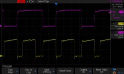
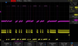
I took a nice screen capture of the 2 MHz while the system was running OK.
Trace below shows the asymmetrical 2 MHz clock in the top trace, bottom is one of components of the 2MHz
I'll wait till it goes into the sticks again and get another capture.
Maybe the light will appear.
I am still commenting my bit of code. Will try to pass this on ASAP.
Don't have a song for tonight.
If you don't have those 5.25 IMDOS image files maybe you have a song ....
MPU-B-Serial-Clock-Top-Trace.JPG
 
This is my weak code to write a 5.25 disk with a DIO/PDS card setup . I tried to make notes where changes would be made to support 8" drive; maybe only I can understand them. I tried to make a constants area to hold some of of the variables to make the code more portable; I need to do a bit of work on this.
None the less I have been able to write tracks and validate them through only the "monitor" commands and calls to the DIO firmware entry points.
I would use Teraterm and a alt-v to write the areas in memory, 0x3200 for my code, 0x3300 for clean-up and 0x3400 for constants.
I would then call the 0x3200 top of my code.
I have been trying to use an 8" image and changing the 8" entry points to the mini-disk entry points, nothing more.
I have been trying to use an 8" image named "imdos205r1-peters" I grabbed from somewhere - Thanks
I started out with blank diskettes so my first endeavour was to format the disks, this is on the format code tab of my spreadsheet & the "Version 3" of my text doc; the version 4 is the write area of the code.
I did the write code where 0x2000 to 0x2ffff would be the write data
(I should have made it larger, this is only like 32 sectors on a mini drive with 18 sectors)
(If my serial port didn't suck, or I was smart enough to fix it I would make it larger)
I was able to re-write the 0x2000 to 0x2FFF area multiple times and then re-execute my code with residual values in the constant area to program more sectors, but it won't seem to boot.
I think there may be some constants in the low area of the image that my be incompatible with my configuration.
Does this seem like a bunch of gibberish? I'm trying.
PS - I am NOT a programmer.
Back to those sh%%%% Minneapolis performers with Dave G:
 

Attachments

  • MFormat4b.zip
    62.2 KB · Views: 1
Last edited:
Still having serial port issues.
I found a different 6 MHz crystal at my local surplus store.
I know crystals can have different characteristics, but what the heck, I tried it yesterday.
The serial port seemed to go flaky in less then a few hours.
Frequency in and out of the 8085 looked OK; still a bit puzzled about this.
I went back to the original crystal.
I hate resoldering in the same place...
What I am lacking is a bit of simple science / data.
This AM I powered it up and started my timer on my phone.
It ran for ~ 6.5 hours with repeatable displays of memory, but then I started seeing a bit of junk on the output.
I looked at my 6' serial cable routing (I am running async, only Tx, Rx, GND, and chassis connections) and it was running past the power transformer.
I re-routed my serial cable away from the chassis and fired it back up again to see if I can beat the 6.5 hour failure point.
As a parallel effort I have a 2x bank of external Shugart SA800 SD 8" drives; I am postponing getting my 5.25 drives going.
I have a few images of 8" drives, why fight it.
Cleaned the internals of the enclosure last night and started to put it back together.
The drive enclosure has an old Power-One linear (I believe) supply with three output voltages.
This seems to be unique to this application, +/- 5.0 and +24 vdc.
I reformed the large 9300uf 50vdc cap some time ago, but there are other electrolytics I am worried about.
I'll check the big one again and install and check resistance on the others.
Next will be to add a few load resistors and see how the DC looks.
In my free time I will be inspecting the drives, cleaning the heads, checking resistances before installation.
With my code chunk I posted I can change from the SA400 to SA800 with a couple of tweaks, so I hope to be able to format and
start writing code as soon as the mechanical and power diligence is done.
Serial port is still chugging as I write, hope I can say the same in the AM.
If you don't send a song you'll have to put up with mine ...
Al
 
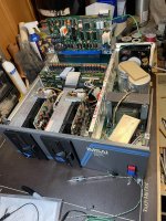
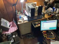
Well - Silly I have not posted this before.
Here is the system with a RAM-32 card installed.
As I said before I also have 2x RAM-16 cards plus some other cards.
Has a DIO/PDS disk controller as noted way above.
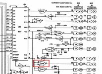
The MPU-B rev 1.2 has some wires on the back on U18, but maybe one or more others.
I am looking at the RS232 transceiver now (U41, blue chip clip). It seems to get narrower pulses out on the interface as it warms up.
(PS - Green wire to the MPU-B card is the earth ground to the chassis; didn't want to blow my sons old PC I have been using.
There is a female socket on the back of the MPU cards for adding earth ground to the RS-232 interface).
I used my VIO card initially with an old video monitor that I could adjust the sync to match the VIO.
I used this to validate getting the system up, getting to monitor, and test the RAM cards.
Because I wanted to write the ram I went to the serial I/O so I could ctrl-v code strings into RAM.
I just have one serial port connection to the MPU.
No parallel port is needed because I am not using the (somewhat) original parallel port keyboard,
just Teraterm and the serial port via a PC.
...
With this configuration I can use the crude code I wrote (above) to format and write the 5.25 disks, but because
I am using an image from an 8" disk system I think I am running into issues.
Writing and reading from the 5.25 disks seems to work though.
(all via monitor).
...
Worked on the 2x Shugart SA800 chassis last night.
I wish there was a terminal buss for the AC wiring rather than point to point soldering.
I put it back together as is, but will have reluctance if the PS gives me trouble.
...
Excuse the work in progress photo (so what is it?, maybe a PCS-80/25).
Now I can put the scope probes back on.
Thanks for the question, I've been in a desert of replies.
Al
System-Photo-c.JPG
 
Last edited:
Above U41 should have been U40, 75188, Tx output 8 seems to stop matching inputs 9 and 10 exactly. Pulses on the output shrink.
This takes a while to happen. I'm checking the +/- input voltages as soon as it flakes out tonight.
U40.JPG
 
I am going to replace U40.
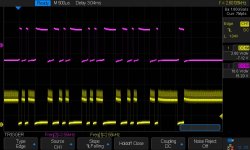
Below I show that U40, essentially an inverter that converts TTL to RS232 compatible signals, progressively gets narrower high output pulses.
I ordered one off the bay today.
The part in the PCA is an Onver QC 1488, but the schematic says it should be a 75188.
I ordered a TI SN75188N; I expect it to be compatible.
Just try to look up the part installed, or even Onver; I see references to Onver in old PC periodicals, and the part, but no data sheet I could find.
...
The SA800 power supply ran overnight with somewhat light load resistors.
The 24 vdc supply should be capable of 1.3 amps per drive, which is 31 watts.
62 watts is a bit difficult to load the supply to; things get pretty warm.
I tested at only 3.6 watts, over 200F on my 160 ohm resistor.
I tweaked up the +5.0 vdc only so slightly.
...
I started cleaning SA800 drive 1 with alcohol, air, and a bit of Deoxit.
I am going to give it a shot later this week (time for some cabin time and fishing).

Top trace is U40 output, bottom is pins 9 and 10, compare to below and you can see this photo has these narrow positive pulses.
U40-Bad.JPG

Good output:

U40-Good.JPG

I should have tried some cold spray. Maybe before replacement to try to ensure I am making a good choice.
Al
 
We had rain and wind most of the time at the cabin; my curse this year.
Didn't catch a fish for the first time ;-{
My 75188 didn't arrive; almost like coal at Christmas, maybe tomorrow.
I tried formatting an 8" drive before I left and was getting drive not ready (error code A1 I recall);
I think I was rushed and may have had the disk in upside down.
Came home with full spirits after all the fish I didn't catch and gave it another bang again.
With the disk in correctly I started looking at index and data out from the Shugart, test points 10 and 1 respectively.
I could see index and data and data, so I gave my format code another shot.
I seem to be able to format SSSD and it seems SSDD drives to SSSD.
I will have to read a few sectors later and see if it is working.
My format code seems to be working.
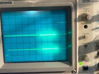
Photo of the mess, scope with index on the bottom and data out on the top.
Tomorrow time to try writing the 8" images and see if I can get anything out of this beast.
Al


IMSAI-8-Formats.JPG
 
Back
Top