• Please review our updated Terms and Rules here

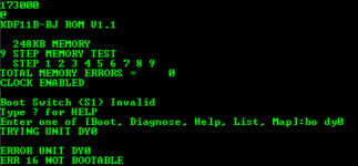
M8189 bootstrap error LED's D1 and D4 on

Hopefully he can fix the issue with slot 3 easily. Maybe just a pin that's stuck out. Or something wedged into the slot keep the pin from making contact. I'd look in there with a very bright light to see if there is anything that can be seen. Or possibly a bad solder joint on the connector? Seems less likely.
I had a UNIBUS backplane where one of the connector tabs popped out a bit, and the next time I put a card in that slot it mashed the connector down into the bottom of the block. No way to fix it of course. Had to mark that slot as DNU. So now I do a bright flashlight inspect anytime I am going to insert a card into a slot, even if I just removed it. So beware. Backplanes don't grow on trees these days, harder and harder to find.
 
>>> Backplanes don't grow on trees these days, harder and harder to find.

I had a very similar "mashing" situation with a backplane connector. Not mine though, I just helped find the damage...

I had an interesting "discussion" with an ex. DEC repair engineer once. He wondered why I was building a UNIBUS backplane tester. In his day they would just replace the backplane. It was much cheaper than repairing the faulty one. All well and good I say, but where do I find a replacement backplane for my PDP-11/45 that I can afford these days! Fair cop he said...

Dave
 
@cmao - I'll send you an M9047 for the cost of postage - PM me with address info if interested. You've put enough sweat equity into this venture to have earned it!
jack, private/direct email sent. I am so lucky to have valuable comments from PDP-11 experts and experienced PDP-11 users
who quickly bring me to PDP-11 world. All my hardware components were obtained form the eBay with the cheapest prices.
The learning path for me is very long but successful so far. I am not far away from booting Don's RX02 emulator to run RX-11 system. My next achievement will be to boot DE10-nano based RL02 emulator (Reinhard Heuberger sent me the gerber file and the interface board to DE10-nano had been built).:)
 
I had a UNIBUS backplane where one of the connector tabs popped out a bit, and the next time I put a card in that slot it mashed the connector down into the bottom of the block. No way to fix it of course. Had to mark that slot as DNU. So now I do a bright flashlight inspect anytime I am going to insert a card into a slot, even if I just removed it. So beware. Backplanes don't grow on trees these days, harder and harder to find.
Don, I have little progress in booting M8189. I record both outputs from RX emulator and M8189. What could be the issue ?

1684788219935.png

1684787911976.png
 
Hmmmm, well, that is not even close to correct for the RX02_EMULATOR monitor log.

I have several different emulator monitor and console boot logs here:

Here is the relevant start of a PDP-11 DY boot monitor log.
Normally the boot will start with read commands to track=1/sector=1 (which is logical block zero on the floppy disk image).
Some boots (like this one) try single density first, and if it errors, then go to double density.
Then you should see a repeating pattern of read sector commands followed by empty buffer commands.

Your display shows a completely nonsensical command (7622) which indicates to me either your cable or RXV21 controller is messed up.

Code:
RX: waiting for INIT to clear ... t=23992ms
RX: INIT has cleared t=24087ms
RX: INIT rx_xmit_es(0244)

RX: cmd=0007
RX: RDSECT unit=0 den=S
RX: RDSECT sa=001
RX: RDSECT ta=001
RX: RDSECT rx_xmit_es(0060)

RX: waiting for INIT to clear ... t=24111ms
RX: INIT has cleared t=24206ms
RX: INIT rx_xmit_es(0244)

RX: cmd=0407
RX: RDSECT unit=0 den=D
RX: RDSECT sa=001
RX: RDSECT ta=001
RX: RDSECT pos=6656. len=256.
RX: RDSECT rx_xmit_es(0040)

RX: cmd=0403
RX: EMPBUF unit=0 den=D
RX: EMPBUF wc=200
RX: EMPBUF rx_xmit_es(0000)

RX: cmd=0407
RX: RDSECT unit=0 den=D
RX: RDSECT sa=003
RX: RDSECT ta=001
RX: RDSECT pos=7168. len=256.
RX: RDSECT rx_xmit_es(0040)

RX: cmd=0403
RX: EMPBUF unit=0 den=D
RX: EMPBUF wc=200
RX: EMPBUF rx_xmit_es(0000)
 
Hmmmm, well, that is not even close to correct for the RX02_EMULATOR monitor log.

I have several different emulator monitor and console boot logs here:

Here is the relevant start of a PDP-11 DY boot monitor log.
Normally the boot will start with read commands to track=1/sector=1 (which is logical block zero on the floppy disk image).
Some boots (like this one) try single density first, and if it errors, then go to double density.
Then you should see a repeating pattern of read sector commands followed by empty buffer commands.

Your display shows a completely nonsensical command (7622) which indicates to me either your cable or RXV21 controller is messed up.

Code:
RX: waiting for INIT to clear ... t=23992ms
RX: INIT has cleared t=24087ms
RX: INIT rx_xmit_es(0244)

RX: cmd=0007
RX: RDSECT unit=0 den=S
RX: RDSECT sa=001
RX: RDSECT ta=001
RX: RDSECT rx_xmit_es(0060)

RX: waiting for INIT to clear ... t=24111ms
RX: INIT has cleared t=24206ms
RX: INIT rx_xmit_es(0244)

RX: cmd=0407
RX: RDSECT unit=0 den=D
RX: RDSECT sa=001
RX: RDSECT ta=001
RX: RDSECT pos=6656. len=256.
RX: RDSECT rx_xmit_es(0040)

RX: cmd=0403
RX: EMPBUF unit=0 den=D
RX: EMPBUF wc=200
RX: EMPBUF rx_xmit_es(0000)
RX: cmd=0407
RX: RDSECT unit=0 den=D
RX: RDSECT sa=003
RX: RDSECT ta=001
RX: RDSECT pos=7168. len=256.
RX: RDSECT rx_xmit_es(0040)

RX: cmd=0403
RX: EMPBUF unit=0 den=D
RX: EMPBUF wc=200
RX: EMPBUF rx_xmit_es(0000)
Do you have a list of cmd's so I can look up the meaning in case I have other commands in future testing?
 
I suspect that my 9-slot backplane needs termination to be inserted in slot #9. There are no resistors or sockets for resistors on my backplane. Can someone confirm that the termination is an important configuration ? If the termination is required, where to find schematics to manually add resistors to backplane. Thanks
 
Are you sure there is not any termination resistors on your backplane? You are looking for single-inline resistor packages.

The schematic for the BDV11 bootstrap card (containing a terminator) is here: http://www.bitsavers.org/pdf/dec/qbus/MP00489_BDV11_Sep77.pdf.

This is a quad card of course.

Dave
Yep. I am sure no resistors including single-line resistors on my backplane. so...the termination is required. correct ?
 
> I suspect that my 9-slot backplane needs termination to be inserted in slot #9.

I guess from @daver2's document, that if there are resistors, and if no cards are inserted, then the level of tension on a pin would be ~3.5 volts.
 
> so...the termination is required?

Termination is used to damp the reflection of signals on the end of a bus, otherwise, it bounces back and messes with the emitted signal. As I remember this effect is particularly strong if the travel time of the signal is shorter than it's rising and lowering times.
This means than for one-meter (~yard) length, the edge times should be (roughly) slower than 5 nanoseconds as electricity travels at ~200.000km/sec.
But in TTL signals, edge times are at ~5nanoseconds, so there is a need for resistors.
(sorry for my broken English)
 
>>> I guess from @daver2's document, that if there are resistors, and if no cards are inserted, then the level of tension on a pin would be ~3.5 volts.

Yep.

Dave
 
Back
Top