• Please review our updated Terms and Rules here

Need help with IBM 5151 monitor troubleshooting

VERAULT

Veteran Member
Joined
Jan 30, 2012
Messages
8,473
Location
Connecticut, USA
So I bought a 5170 AT recently and the unit is "short city" Everything in the unit and cards has shorts.

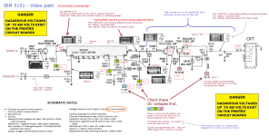
The IBM 5151 monitor was DOA as well. I thought I had it down to the TR24 MJ2955 PNP Power Transistor but that was a red herring. I followed the SAMS 5151 VDU troubleshooting and got to the point where it wanted to check:


"Check the sources that are developed from Transformer T502. Check for 56.8V at the cathode of Diode D503 and 546V at the cathode of Diode D505.

I get 14.8V at the cathode of D505 and I get 0.38V at the cathode of D503

I am getting 0.33 OHMS on the Horizontal Coil
and I am getting 4.11 OHMs on the Vertical coil

I am getting 1.0 OHMS on the "RED" TR801 power transformer coil

I am getting 17.1 OHMs on the TR801 Coil "BLACK" winding

The heater is glowing, I get no high voltage, no high pitched squeal. I get no raster of any kind.

Could use some help on this.
 
Last edited:
Are you giving it an MDA signal of some sort? The 5151 needs a signal before it generates high voltage.
 
Ok some progress but still not working.
I replaced the 7815 and I now get Raster. I get NO video at all though. I was reading here that Ic201 which is a 7406 can sometimes affect contrast issues. I popped it out and socketed it. Tested the IC it tested fine. I tried another 7406 and made no difference so that was unecessary.

I also mesured the resistance of the contract pot. IT was scratchy and uneven but I cleaned it up and it still made no difference. Only the brightness knob seems to have any affect but that just may because I am seeing no video.

So the MDA card that came with this 5170 was shorting out when I put it in the computer (psu wouldnt turn on). I replaced the 5 tantalums and it no longer is shorting out the computer however when inserted obviously I get no video but I get a few beeps as soon as the machine begins to post. My other MDA card isnt causing those beeps so I suspect the original MDA card still has a fault.

AnywayI have working MDA and herculese cards and still get no video from the 5151, but I do have raster now.
 
The B+ voltage would actually rise. My power transistor was "leaky"

It made the raster shaky and all kinds of distorted
 
You now have a raster, and you will have verified that the front-panel CONTRAST control was not turned down, so the symptom remaining (raster but no video) is probably somewhere in the video path.

The circuitry for the video path is at [here].

A logic probe on pin 9 of the SN7406 will reveal whether or not the video signal is making it to the SN7406.

After that, a multimeter alone may be enough, comparing your DC voltage measurements to the many shown in the diagram.
Allow too for a poor connection between pin 2 on the CRT and the mating PCB.
 
So I decided to not futz around with probably bad parts. I took my AMDEK 310A monitor out of storage since it works and tested all my MDA cards. Sure enough they all work fine except the one that came in the 5170 (packaged with this 5151 monitor)

So I AM using a good card for testing.

Again we have raster but no video.

@modem7 using your checks I added the voltages and notes I found in RED to this image (sorry my text is so tiny) . I blew out the soldered on .75A 25V fuse so I installed a fuse holder and replaced the fuse.
Everything seems within spec. Except the note about the 30VPP contrast setting in the upper right. Im at a loss why I cant see video on the screen.
5151_video_path.png
 

Attachments

  • 5151_video_path.png
    5151_video_path.png
    293.1 KB · Views: 8
Last edited:
Except the note about the 30VPP contrast setting in the upper right. Im at a loss why I cant see video on the screen.
A logic probe is unsuitable for measuring most of this circuitry. For example, in measuring pin 2 of the CRT, you have exposed your logic probe to a DC voltage of about 50V. The designers of your logic probe are not expecting that, and are expected to have the parts within your logic probe voltage rated to handle TTL (5V) signals. For example, a logic probe is not going to inform you of the actual amplitude of pulses on pin 2.

Re your "Testing R207..." So when you turned down the contrast control, your logic probe will have showed a LOW and no pulsing. As you turned up the contrast control (i.e. slowly increasing the pulse [video] amplitude), a point will have been reached when the logic probe showed the presence of pulses. Correct? If so, it's a good sign, but it only informs you that the pulses got over about 2 volts amplitude (TTL HIGH threshold). An oscilloscope will confirm that the base of the signal is about the 0V mark, and the amplitude of the pulses.

The DC voltages look okay.

Re your "I see no variation ..." comment. I, under no circumstances would trust what a logic probe shows there. Hopefully, you didn't damage yours.

Did you remove then refit the PCB from/to the CRT, in case of a bad connection between pin 2 of the CRT and the mating contact. Bad pin 2 solder joint on the PCB !

Where to now? What DC voltage do you measure on the base and emitter of TR19 ?

Are you in a position to borrow an oscilloscope from someone. Of course, you will have a bit of a learning curve to use it.
 
Its a cheap logic probe.. ITll be fine! :cool:

Yes The connection to the neckboard was checked and refitted.

As to R207,, Yes it was pulsing, then it just went low. But now that you posed the question I feel like I forgot what it was doing and dont recall now! But I feel it was doing just what was explained on the diagram.

I will get back to you tomorrow with the TR19 voltages.

Yes I can get an ocscope.. nothing fancy. What Should I check.
 
Last edited:
Yes I can get an ocscope.. nothing fancy. What Should I check.
You have changed IC201 (presumably with a good one), and verified that TTL pulses (video at TTL levels) are arriving at input pin 9. So, the target is what is after IC201.

The PCB on the CRT is very easy to get at. So, I would say, first up, look at pin 2 on the CRT. Sitting at about 50V (expected because of your DC measurement) with negative-going pulses (the video), the pulse amplitude being as expected (amplitude, and amplitude varying from 0 to about 30V depending on the contrast control setting).

If that is not what you see, I would go back to pin 8 of IC201, to verify that it is behaving as expected. If so, you then follow the path from pin 8 of IC201 to pin 2 of the CRT.
 
Ok @modem7 I am not getting anything I can see other than the slightest ripple at the 54.3V I measured at CRT pin 2.. So thats no good. Adjusting the contract pot makes no change to what I see on the scope on CRT pin 2

as far as TR19 I get .006V from the Base and .008V at the emitter and as mentioned in post #13 I still get 6.6V at the collector.

I see no waveform at the Base of TR19/R208 even though its present at R207


The graphic you have mentions the contract control will affect the Pulse amplitude and it does I can get between .8V to 5.2VPP


My Oscope works but its very dim, I can see the waveforms but I need to find the subbrightness and dial it up as the pulses are faint, but I can still see them.
 
Last edited:
"My Oscope works but its very dim, I can see the waveforms but I need to find the subbrightness and dial it up as the pulses are faint, but I can still see them."

You're treading on thin ice. Fixing old oscilloscopes can be another hobby that will suck in the unwary.

;-)
 
I see no waveform at the Base of TR19/R208 even though its present at R207
The graphic you have mentions the contract control will affect the Pulse amplitude and it does I can get between .8V to 5.2VPP
as far as TR19 I get .006V from the Base and .008V at the emitter and as mentioned in post #13 I still get 6.6V at the collector.
With power off, measure the resistance between pin 8 of IC201, and the base of TR19. You are expecting roughly 70 ohms. If much larger, or infinity, you need to work out where the break is.

If no break:

If I think, maybe TR19 has a short between base and emitter, the circuit suggests to me that you would still see pulses on the base, about half the amplitude of what is seen on pin 8 of IC201. Nonetheless, I suggest that you remove TR19 from the PCB then test it. There is lots online on how to test a transistor with a multimeter. A lot are confidence only because to do it properly, it would go into a transistor tester, which also tests things like gain. But in the vast majority of cases where I have encountered a faulty transistor, the diode test functionality of a multimeter has been enough to show the transistor as faulty.
 
Back
Top