daver2
10k Member
Use Google to search for "Zimmers Commodore PET schematics" and you will find most of the schematics for the Commodore PET series of computers.
Dave
Dave
Thanks! Looks like the schematics needed for this PET are in: http://www.zimmers.net/anonftp/pub/cbm/schematics/computers/pet/8032/index.htmlUse Google to search for "Zimmers Commodore PET schematics" and you will find most of the schematics for the Commodore PET series of computers.
Dave
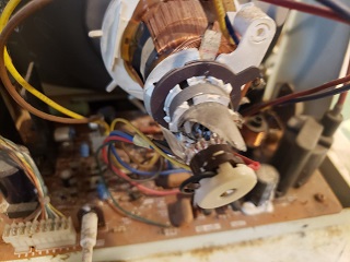
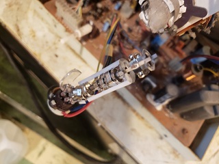
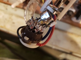
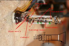
Sure here are a couple photos of the gun from the side (I won't bother making thumbnail size photos of these two):can you take a photo of the gun directly side on. And also have a look to see if any of the electrodes in the array were connected together.
I have drawn a diagram, but just to double check that it is correct, can you take a photo of the exact opposite side of the gun as shown in your image1, because sometimes there are variations, where the structure labelled as the left hand Green X is connected to a base connection and not A2.
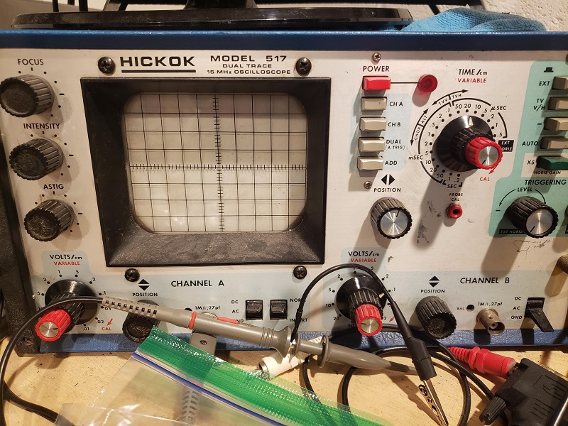
not much, an old CRT oscilloscope and a multimeter.What test equipment do you have access to out of interest?
Dave
That is more than adequate. You should be able to check the majority of signals depending upon exactly what scope you have. Can you let us know what you have so we can find the manual?not much, an old CRT oscilloscope and a multimeter.
oh I'm glad you said that i had read another post on this forum where someone said it was a slow blow fuse. I'm in the us so I'll be running at 110 volts.That is more than adequate. You should be able to check the majority of signals depending upon exactly what scope you have. Can you let us know what you have so we can find the manual?
The fuse is a fast blow (not a slow blow) but it depends upon what mains voltage you are running the PET on. 110V or 230V.
Dave
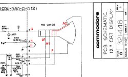
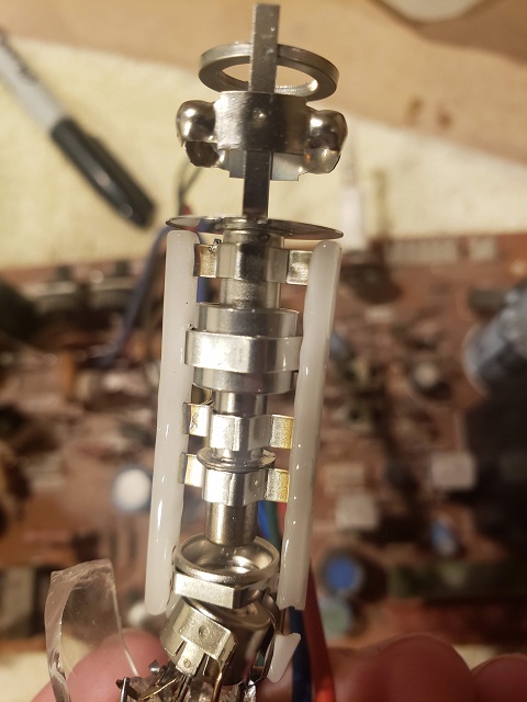
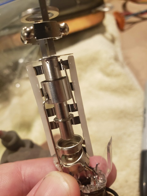
The gun configuration is standard as as I indicated in my first diagram. Likely, the Amber CRT is the same. So it is only a matter of looking at it and verifying the pin connections (after the heater voltage was checked, that is likely 12V) If the heater current was different the resistor in series with the heater in the PET VDU can be altered to give 11V to 12V across the heater terminals while running. If, in the off chance it was a 6.3V heater in the Amber CRT, the resistor could simply be increased in value and power rating.
When you are repairing the pet, you can leave the VDU disconnected, initially at least, and check that the 60Hz (vertical) and 20kHz(horizontal) drive pulses are arriving at the VDU board with the scope, before you power the VDU.
I read that the Samsung set has a H frequency of 18.4 kHz (is that true ?) if it is is would still work with the PET signal adapter, but with the slightly higher H frequency it might or might not pull into horizontal hold (it probably would or could be made to) The picture width would be a little less than normal, but, that could be increased with the Width control inductor.
So you have two ways to go. I would fit the Amber CRT tube and keep the original PET VDU board, for originality, but that is just a preference because I'm comfortable substituting CRT's.
Ignore the image gun.jpg below I attached it by accident, haven't figured out how to remove it yet.
I drew in the electrodes around the Focus cylinder that are often omitted in schematics.
Ignore what I stated in post #32.oh I'm glad you said that i had read another post on this forum where someone said it was a slow blow fuse. I'm in the us so I'll be running at 110 volts.
about the scope, sure I'll post it tomorrow morning, I actually don't remember the model, it's something i picked up at habitat for humanity.
oh okay good that's what I had in my amazon shopping cart. I think I need to just study all the docs on that site while I'm waiting for stuff to arrive: rgb2hdmi cable parts, rust converter, fuse & socket, etc...Ignore what I stated in post #32.
I have just got back from holiday and checked my documentation at home and it is a 1.6A SLO-BLO for 110V... See F1 on http://www.zimmers.net/anonftp/pub/cbm/schematics/computers/pet/8032/8032051-2.gif.
Dave
It doesn't take much. I don't know if you watch The 8 bit Guy on youtube, but his most recent video was of his attempts to repair an old arcade cabinet. He had to remove and install the picture bulb, and he accidentally --tapped-- the neck against the cabinet. Pop whoosh, the CRT was destroyed.Nope the implosion band is still there. The guy who sold me this says it got dropped.
Yeah I saw that video a few days ago, I was thinking: That looks familiar!It doesn't take much. I don't know if you watch The 8 bit Guy on youtube, but his most recent video was of his attempts to repair an old arcade cabinet. He had to remove and install the picture bulb, and he accidentally --tapped-- the neck against the cabinet. Pop whoosh, the CRT was destroyed.
Please please please be careful handling that old CRT! You do NOT want chromium poisoning! You should not be handling it with your bare hands, nor should you work on it anywhere near a living area. The dust could get all over the place, and get into your lungs.