• Please review our updated Terms and Rules here

Pet 3032 Vertical Collapse

The only other pot (other than brightness) is the vertical size. This monitor also doesn't have a pot for the focus either. Pared right down to the bone!

Now I have mentioned the vertical size pot - your problem isn't associated with this potentiometer going faulty is it?

Dave

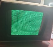
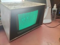
Thanks Dave, that was a good thought because originally the brightness pot was a bit dodgy and there was nothing on the screen. After working it back and forth a little, with a bit of elec cleaner, the horizontal line appeared. I've removed the v. size pot and checked it and seems to be good.

....

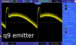
There are a few ways you can do this, disconnecting one of the CRT's heater connections will work as that kills the electron emission. But probably the easiest way is to disconnect the H drive pulse, this will simultaneously kill the high voltage supply, kill the EHT and the H scan too. Simply lift one leg of the H drive input coupling capacitor C16 from the pcb. And connect up last thing after the V scan fault is fixed or at least you have some vertical scan. So there will then be no -30V, no +85v and no 10kV EHT and the horizontal driver transistor Q13 and H output transistor Q14 will both be in a non conducting condition. The CRT heater will still be glowing with no other voltages on its other electrodes, this does not harm it. But, the V scan stages do not depend on any of these voltages, only the +12V. This will also make it safer for you to work on too.

Thanks Hugo, sounds like a good plan! Disabling the higher voltages while working on the pcb is more appealing!

I think I have also confirmed that the VDU pcb is video-3.gif as it uses a 47uf cap at C22 on the board I have.

Really enjoying troubleshooting this pet! Hope to see it all working again soon :)

Cheers

Matt
 
I think I have also confirmed that the VDU pcb is video-3.gif as it uses a 47uf cap at C22 on the board I have.

Really enjoying troubleshooting this pet! Hope to see it all working again soon :)

Cheers

Matt
At some stage you can replace that capacitor C22 with a 220uF 63V 105 deg C type.

I made a few other mods to my 9" PET VDU, because I was not 100% happy with the peripheral CRT beam focus and H scan linearity, but I probably went further than most would like to go because I get a little obsessed making VDU's work as well as they can, I documented it, including restoration of the rusted housing with the aid of Fertan:


As Daver2 noted these 9" VDU's are a very minimalistic design, that were devoid of luxuries like H width and H linearity controls and focus adjustments. The result is ok, if you don't mind those issues not being perfect.

They push the 7812 voltage regulator in this VDU fairly hard, so it is worth making sure that it is well thermally bonded to its large heatsink. In one VDU repair case we have seen on this forum, where the metal tab of the 7812 was riveted down, there was distortion in the tab and a paucity of thermal paste, so the 7812 overheated and periodically went into thermal shut down. I see yours has a screw & nut and a good amount of compound which is helpful.
 
I've probed q8 and q10 base as per the test points on this schematic and get the following wave forms. I think the timing on q8 is off a tiny bit, but the q10 base looks sus.

What should I check from here?

Cheers

(Sorry about the phone pic, for some reason the scope didn't want to save the waveform to usb)
Edit - inserted q9 base
 

Attachments

  • vdu q8 base.jpg
    vdu q8 base.jpg
    244.9 KB · Views: 4
  • vdu q10 base.jpg
    vdu q10 base.jpg
    212.6 KB · Views: 4
  • vdu q9 base.jpg
    vdu q9 base.jpg
    243.1 KB · Views: 5
Last edited:
Just realised I didn't check the adjustment on R20 after removing and rechecking it. If I adjust it I can get q8 base to 0.2ms. I think it might be inverted though looking at the schematic?
 
I,m on a tiny phone keypad till tomorrow.
One thing is to make any sense of scope recordings presented to others, the scope should be on dc coupling, the timebase time per division has to be noted and the vertical volts per division noted and also where the scope beam started with no signal.Typically this is on the screen centre line, but you need to say where it was. Otherwise without this information it is not possible to interpret the traces properly.

Thanks for getting back to me Hugo. Sorry about the lack of information in the photos. On all of them the v/div is set to 500mv, q8 measurement timebase is set to 2ms, q10 is 8ms, and q9 is 4ms. The starting point is the vertical centre, and the scope is on dc coupling.

Cheers
 
Think I found the problem... q10 is testing bad. Will have to see if I can find a replacement now and see if that fixes it! :D
 

Attachments

  • q 10 bad!.jpg
    q 10 bad!.jpg
    184 KB · Views: 9
I went ahead and replaced q10, and now I'm getting better looking signals, but still not working... Looks like more troubleshooting to do! One thing I do notice, is the vertical signal is rock solid of the mainboard connector (J7) without the monitor cable plugged in, but when it's plugged in it seems to move around a bit like it doesn't trigger properly... Maybe a bad cap somewhere?

Sorry for the recent spamming :|

Cheers :)
 

Attachments

  • q10 base.jpg
    q10 base.jpg
    103 KB · Views: 0
  • q9 base.jpg
    q9 base.jpg
    208 KB · Views: 0
  • q8 base.jpg
    q8 base.jpg
    105.9 KB · Views: 0

I went ahead and replaced q10, and now I'm getting better looking signals, but still not working... Looks like more troubleshooting to do! One thing I do notice, is the vertical signal is rock solid of the mainboard connector (J7) without the monitor cable plugged in, but when it's plugged in it seems to move around a bit like it doesn't trigger properly... Maybe a bad cap somewhere?

Sorry for the recent spamming :|

Cheers :)
It looks like q10's base is ok in the form of the wave. Check q10 emitter(the amplifier's output) and see if the amplitude matches the schematic. The vertical stages may well be working to some extent now, so you could reconnect the H drive coupling cap and inspect the scan on the CRT face.
 
>>> One thing I do notice, is the vertical signal is rock solid of the mainboard connector (J7) without the monitor cable plugged in, but when it's plugged in it seems to move around a bit like it doesn't trigger properly... Maybe a bad cap somewhere?

Good work so far.

Unlikely to be a bad capacitor if you are going directly on J7. Can you post an oscilloscope trace of the J7 V DRIVE signal without the monitor connected. Please make sure you set the oscilloscope timebase appropriately though. I assume you are debugging your monitor with it connected to J7 though - so I can't see why the V DRIVE on J7 is not a nice TTL signal itself...

Dave
 
I think I worked out why the vertical signal was going out of wack... I feel really stupid but I put a capacitor that I removed for checking back in backwards...

Anyway, after fixing that the v.sync is looking nice again even with the monitor connected - same as my original post. After a bit more mucking around and switching on and off a few times to reposition things, it worked! Had a good image! The monitor was working but the computer wasn't but that is for a later stage... And then as quick as it came it went after a few minutes. :(

Any ideas why it might have worked for a moment?
 

Attachments

  • working!.jpg
    working!.jpg
    33.3 KB · Views: 11
>>> Any ideas why it might have worked for a moment?

A million different things. But at least you now have a stable picture. Yes?

The next place to check with your oscilloscope is on the 6502 CPU.

Pin 2 (RDY) should be HIGH.
Pin 4 (/IRQ) should either be HIG or pulsing - put not permanently LOW.
Pin 6 (/NMI) should be HIGH.
Pin 7 (SYNC) should be pulsing (if the CPU is executing instructions).
Pin 38 (SO) should be HIGH.
Pin 39 (/RESET) should be LOW when you first turn the PET on, and then go HIGH after about half to one second.

Let's see where that takes us.

The usual cause of not starting up could be faulty RAM or ROM - but it could still be a host of other things as well - so we can't jump to conclusions... Let's work the problem.

Do you have the capability for burning EPROMs?

If so, we probably need to look at you getting a copy of my PETTESTER code and burning an EPROM. This would be exchanged for the EDIT ROM (which should be in a socket) on your board. This only requires the bare minimum of hardware working to start testing stuff... We will need to know what ROM types are fitted to your particular machine.

From your photograph I am guessing you may have some video RAM faults - but we won't know that for sure until we get PETTESTER running and it will tell us.

Another possibility for intermittent operation is rubbish IC sockets and the build up of dirt and oxides on the pins.

Dave
 
Sorry Daver2, I was meant to say the monitor worked for a few moments, but it has now gone blank again - so no stable picture atm.

Getting late here now, so I'll do some more checking in the morning.

Thanks for all your help so far everyone :)
 
On these vdu's they can get 360 degree ring cracks on the soldering between their connector pins and the pcb making the vdu intermittently cut out, so visually inspect that.
Also check that the H drive signal and the 12v supply is still good .
 
About that issue of backwards caps,in the 9 inch vdu, you can do a quick visual check because every electrolytic has its negative connection facing in the same direction,toward the rear of the board, which is unusual for a vdu, where mostly they face every which way.
 
Well it seems to have fixed itself overnight! The screen is displaying a picture again, but it seems a little bit shaky. I probed q9 emitter, and signal seems to be noisy. Could this indicate a bad capacitor? I had a good look over the board and the solder joints seem all good.
 

Attachments

  • q9 emitter.jpg
    q9 emitter.jpg
    288.9 KB · Views: 1
Just another update, I was fiddling with it again a bit more today and I think I now have it working! I thought the brightness pot was all god, but when I was adjusting it, the image disappeared. If the pot was wiggled though the image would come back. So I removed the pot, gave it a good cleaning and put it back, and so far the image seems to stay on!

I think I can now progress to repair of the mainboard :)

Big shout out to Hugo and Daver2 for their advice, and the nudge needed to head in the right direction! Thanks guys!

I'll probably start another thread to help with the mainboard issue.

Cheers
 

Attachments

  • working take 2.jpg
    working take 2.jpg
    229 KB · Views: 5
Back
Top