• Please review our updated Terms and Rules here

Pet 4016 Transformer Question

ricsne2010

Member
Joined
Apr 4, 2022
Messages
47
Location
Nevada
Hello all.... (first time poster, long time guest ;)

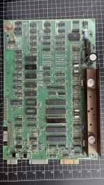
Quick question, I have a PET 4016, 12" CTRC Universal board, runn at 110V AC input, here that Im trying to determine the proper output voltages for...

The schmetics from zimmer.net are helpful, but not enought for me to determine if I have a bad transformer or not....

I have bypassed the old input power plug, fuse, and swithc with one from "amazon" that allows me to connect the L and N line as described in the schematic.

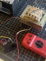
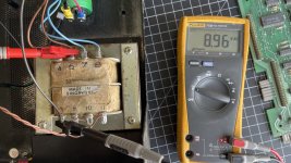
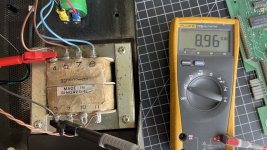
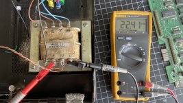
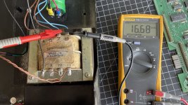
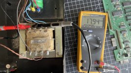
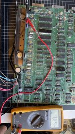
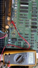
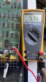
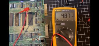
Knowing the transformer puts out 21V AC for the monitor (which is across outputs labeled 9 and 11 on the transformer) - I am at a loss for the blue wires (4 and 6) as well as the brown wires (7 and 8) as to what exactlty they are to put out (when measureed with my DMM, I get 16+ and 9+ respectively) - and different voltages if I measure from the Black (ground) wire from terminal 5 across any of the before mentioned output terminals (either 5 and 4, or 5 and 6, or 5 and 7 or 5 and 8)

I assume the power is sent to an onboard recifier that changes this from AC to DC, which is where we get the +5V DC and -5V DC as well as the 9V and 16V become DC also????

Thank you for any input and comments you all have,

Cheers
Rich
 

Attachments

  • IMG_7721.jpg
    IMG_7721.jpg
    712.2 KB · Views: 5
With the PET and monitor disconnected from the transformer measure (and post) the voltages between the following points:

Two thin brown monitor wires (transformer pins 9 and 11).

Two blue wires (transformer pins 7 and 8).

Black (transformer pin 5) to brown #1 (transformer pin 4).
Black (transformer pin 5) to brown #2 (transformer pin 6).

Two brown wires (transformer pins 4 and 6).

The black wire (transformer pin 5) is the centre tap of the winding connected to the two brown wires (transformer pins 4 and 6). Therefore, when measuring from the black wire to either of the thick brown wires, you should read approximately half the voltage that you measure between the two thick brown wires.

Avoid the temptation to measure from a transformer connection to 0V/GND - it is not helpful...

The two blue wires effectively become the GND/0V and +12V rails (+16V UNREGULATED before the 7812 voltage regulator).

The two thick brown wires and the black wire (centre tap) become -9V (UNREGULATED) and then -5V (via the 7905 voltage regulator) and +9V (UNREG) and then +5V (via the 3 off 7805 voltage regulators).

I have already posted on a number of Commodore PET threads with the readings I have obtained from my PET. Happy to confirm your readings when I get back home.

>>> I assume the power is sent to an onboard recifier that changes this from AC to DC, which is where we get the +5V DC and -5V DC as well as the 9V and 16V become DC also????

The +9V, -9V and +16V voltages are the UNREGULATED DC supplies (after the AC voltage from the transformer windings have gone through the bridge rectifiers.

The -5V, +12V and +5V voltages are the REGULATED DC supplies (after the UNREGULATED DC supplies have gone through the voltage regulators).

I hope this explanation answers your question?

Dave
 
Last edited:
With the PET and monitor disconnected from the transformer measure (and post) the voltages between the following points:

Two thin brown monitor wires (transformer pins 9 and 11).

Two blue wires (transformer pins 7 and 8).

Black (transformer pin 5) to brown #1 (transformer pin 4).
Black (transformer pin 5) to brown #2 (transformer pin 6).

Two brown wires (transformer pins 4 and 6).

The black wire (transformer pin 5) is the centre tap of the winding connected to the two brown wires (transformer pins 4 and 6). Therefore, when measuring from the black wire to either of the thick brown wires, you should read approximately half the voltage that you measure between the two thick brown wires.

Avoid the temptation to measure from a transformer connection to 0V/GND - it is not helpful...

The two blue wires effectively become the GND/0V and +12V rails (+16V UNREGULATED before the 7812 voltage regulator).

The two thick brown wires and the black wire (centre tap) become -9V (UNREGULATED) and then -5V (via the 7905 voltage regulator) and +9V (UNREG) and then +5V (via the 3 off 7805 voltage regulators).

I have already posted on a number of Commodore PET threads with the readings I have obtained from my PET. Happy to confirm your readings when I get back home.

>>> I assume the power is sent to an onboard recifier that changes this from AC to DC, which is where we get the +5V DC and -5V DC as well as the 9V and 16V become DC also????

The +9V, -9V and +16V voltages are the UNREGULATED DC supplies (after the AC voltage from the transformer windings have gone through the bridge rectifiers.

The -5V, +12V and +5V voltages are the REGULATED DC supplies (after the UNREGULATED DC supplies have gone through the voltage regulators).

I hope this explanation answers your question?

Dave
Dave, this is gold... thank you....

The mesurements are below (and I included images to verify I did this correctly LOL)

The "Two thin brown wires" - these being the lines to the 12" monitor = 22.41 VAC

Two blue wires (transformer pins 7 and 8) = 16.68 VAC

Black (transformer pin 5) to brown #1 (transformer pin 4) = 8.96 VAC

Black (transformer pin 5) to brown #2 (transformer pin 6) = 8.96 VAC

Two brown wires (transformer pins 4 and 6) = 17.94 VAC

All of these were read with the motherboard and monitor disconnected - the smoothing CAP (the super large green cylinder) was still connected but doesnt seem to do much without it connected to the motherboard....

I will also include a full hi-res photo of the motherboard - I am not 100% certain this board has been "worked on" before, and if its missing the Editor ROM - but progress is sweet...

I did some prelim "continunity" testing on the Board using the ground attached to the GND of the board and then using my multimeter to test the GND points of each chip/resistor/CAP/ other...

Of that testing, the items circled in YELLOW had good signal / tone from the meter - the two transistors in RED had nothing across any of the 3 legs.... when I looked those up in the schmatics, they appear on the CASSETTE page for the 5V side of the house.... I suspect these are bad and have new one's on order (along with the other items in yellow)

If you have any suggestions as to where to test for power once the Transformer is connected, that is most appreciated.

I saw a reply in another post about pushing the DC through the board via the power plug (where as its already converted to DC) - I will review that and reply there :)

If you see anyting "off" or odd, feel free to PM me....

As always, I cannot thank you enough for your assistance.

Cheers
Rich
 

Attachments

  • IMG_7743.jpg
    IMG_7743.jpg
    1.6 MB · Views: 8
  • IMG_7741.jpeg
    IMG_7741.jpeg
    1.8 MB · Views: 7
  • IMG_7739.jpeg
    IMG_7739.jpeg
    1.8 MB · Views: 5
  • IMG_7736.jpeg
    IMG_7736.jpeg
    1.8 MB · Views: 4
  • IMG_7738.jpeg
    IMG_7738.jpeg
    1.9 MB · Views: 4
  • IMG_7742.jpeg
    IMG_7742.jpeg
    1.8 MB · Views: 6
  • IMG_7743.jpeg
    IMG_7743.jpeg
    1.5 MB · Views: 8
Rich,

Those AC voltage readings look fine to me.

EDIT: Incorrect text below updated (I hope correctly now)!

Transistors Q1 and Q2 are not connected to 0V/GND, so there will be no continuity on any pins of these transistors. You may have purchased spares!

I would disconnect the monitor cable from the PET logic board first, then power up the PET and check to see that the black magic smoke isn’t let out...

Measure the DC voltages from each of the regulators by measuring the voltage across the following capacitors:

C1. This should measure -5V from regulator VR1.

C11. This should measure +5V from regulator VR4.

C7. This should measure +12V from regulator VR2.

Of course, you will have to connect your probes the correct way round to get the sign correct :).

I am hoping I have found the correct (ish) schematic and board layout for your machine. If not, I can specify some IC pins for you to measure tomorrow.

I assume this documentation matches your machine: http://www.zimmers.net/anonftp/pub/cbm/schematics/computers/pet/univ/index.html?

The neck of the CRT should glow dimly. this indicates that the tube heater and basic monitor DC rail is working correctly.

You won’t get a picture on the screen though... This is intentional at the moment! We don’t want to damage the monitor.

You may hear the startup ‘chirp’ if you are lucky.

All the ROMs appear to be fitted though.

Dave
 
Last edited:
Rich,

Those AC voltage readings look fine to me.

EDIT: Incorrect text below updated (I hope correctly now)!

Transistors Q1 and Q2 are not connected to 0V/GND, so there will be no continuity on any pins of these transistors. You may have purchased spares!

I would disconnect the monitor cable from the PET logic board first, then power up the PET and check to see that the black magic smoke isn’t let out...

Measure the DC voltages from each of the regulators by measuring the voltage across the following capacitors:

C1. This should measure -5V from regulator VR1.

C11. This should measure +5V from regulator VR4.

C7. This should measure +12V from regulator VR2.

Of course, you will have to connect your probes the correct way round to get the sign correct :).

I am hoping I have found the correct (ish) schematic and board layout for your machine. If not, I can specify some IC pins for you to measure tomorrow.

I assume this documentation matches your machine: http://www.zimmers.net/anonftp/pub/cbm/schematics/computers/pet/univ/index.html?

The neck of the CRT should glow dimly. this indicates that the tube heater and basic monitor DC rail is working correctly.

You won’t get a picture on the screen though... This is intentional at the moment! We don’t want to damage the monitor.

You may hear the startup ‘chirp’ if you are lucky.

All the ROMs appear to be fitted though.

Dave
OK cool, I'm ok with spares as I have a 8032 and an 8096 board waiting in the shadows ;)

Let me get those points measured and I will report back.

Initial power up = no CRT and no CHIRP from the piezo buzzer on the motherboard...

I will check to see if the CRT neck does glow.... (hopefully it does) - I will report shortly...

Again, thank you for all the assistance!

Rich
 
Rich,

Those AC voltage readings look fine to me.

EDIT: Incorrect text below updated (I hope correctly now)!

Transistors Q1 and Q2 are not connected to 0V/GND, so there will be no continuity on any pins of these transistors. You may have purchased spares!

I would disconnect the monitor cable from the PET logic board first, then power up the PET and check to see that the black magic smoke isn’t let out...

Measure the DC voltages from each of the regulators by measuring the voltage across the following capacitors:

C1. This should measure -5V from regulator VR1.

C11. This should measure +5V from regulator VR4.

C7. This should measure +12V from regulator VR2.

Of course, you will have to connect your probes the correct way round to get the sign correct :).

I am hoping I have found the correct (ish) schematic and board layout for your machine. If not, I can specify some IC pins for you to measure tomorrow.

I assume this documentation matches your machine: http://www.zimmers.net/anonftp/pub/cbm/schematics/computers/pet/univ/index.html?

The neck of the CRT should glow dimly. this indicates that the tube heater and basic monitor DC rail is working correctly.

You won’t get a picture on the screen though... This is intentional at the moment! We don’t want to damage the monitor.

You may hear the startup ‘chirp’ if you are lucky.

All the ROMs appear to be fitted though.

Dave
OK so I have done the measurements ----

As you mentioned its important to get the leads correct on each of the test points, so I have included images to show you what way I had the leads...

For C1, the voltage was + and not -.... based on the leads of the Multimeter being connected with the red/postive and black/negative on that Cap...

The others were all measured the same way using the same color code to + or - on the cap as labeled both on the board and the cap itself...

The readings were done with the MM set to DC...

C1 = +5.13 VDC (again this is based on the MM leads attached as shown on the board, when I reverse then, the meter reading is -5.13 VDC

C11 = +4.89 VDC (MM leads attached as red/positive and black/negative)

C7 = +11.95 VDC (MM leads attached as red/positive and black/negative)

So provided the C1 voltage is proper - then I will need to work my way down to see what the next issue would be...

When power is applied with the motherboard in this configuration (no monitor attached in anyway) - no chirp from the motherboard

(Note, the keyboard is not connected)

The schmatic you sent in the link is the one I have been working with (I too had to somewhat interperlate as the diagrams are various and numerious LOL)

So ........... ??? (just a side note, the only cleaing I have done to the board is from IPA and a soft brush to remove any grime and dirt from the past 40+ years, I have also pulled and re-seated each of the socketed IC's - they are installed with the "key notch" in the correct position - good to know I am not missing any IC's.... )

Thank you again for your help on this!

Cheers
Rich
 

Attachments

  • IMG_7747.jpg
    IMG_7747.jpg
    1 MB · Views: 5
  • IMG_7749.jpg
    IMG_7749.jpg
    985.6 KB · Views: 5
  • IMG_7746.jpeg
    IMG_7746.jpeg
    926.4 KB · Views: 5
  • IMG_7753.jpeg
    IMG_7753.jpeg
    1.1 MB · Views: 5
  • IMG_7751.jpeg
    IMG_7751.jpeg
    965.6 KB · Views: 6
  • IMG_7754.jpeg
    IMG_7754.jpeg
    1,019.9 KB · Views: 6
  • IMG_7752.jpeg
    IMG_7752.jpeg
    1.1 MB · Views: 6
  • IMG_7755.jpeg
    IMG_7755.jpeg
    1.1 MB · Views: 5
  • IMG_7750.jpeg
    IMG_7750.jpeg
    920.5 KB · Views: 5
More boards eh!

Those DC voltages look fine also.

Excellent statement of how you are taking the measurements!

All positive voltage rails will have the negative ends of any polarised capacitor connected to 0V. All negative voltage rails will have the positive ends of any polarised capacitor connected to 0V. If you connect your multimeter positive to positive and negative to negative, you will always read +5V instead of -5V.

When I read DC voltages (using a digital multimeter that is) I connect the multimeter negative lead to 0V and take measurements with the multimeter positive lead. When measuring DC rail voltages the worst case is you measure the wrong side of the capacitor - and read nothing! If you trace the schematic from the output of the regulator to the pin of the capacitor you need to measure, the schematic will indicate which side of the capacitor is which so you can measure the correct side (be that + or -).

I would connect the monitor next to the PET main logic board and give it a try. The usual failure mode of a CRTC PET is no picture of course.

Before I give you the next steps, I have a few questions for you:

1. Do you have an oscilloscope? If so, what make and model?
2. Do you have the capability to burn 2716/2516 EPROMs?

With the oscilloscope we can measure critical signals on the CPU to see what it is doing.

I have developed a PET test ROM that replaces the EDIT ROM. This doesn’t assume that much if the PET is actually working.

A number of VCFED people have developed ROM/RAM replacement cards that fit in the CPU socket. They also contain my PET test code and a useful feature called a NOP generator.

Let’s see how far we get without this ROM/RAM card first though.

Dave
 
(EDITED)

Absolutely great info. Noted on the capacitor measurement side of things (all the more reason why I take the pics so someone can explain a different (I mean "correct") way of taking the measurements ) ;)

As for your 2 questions above,

1. Do you have an oscilloscope? If so, what make and model?
--- sadly the one I have is a super cheapo small LCD / Chinese knock off / probably not really an oscilloscope. This is the one :

DS211 Mini Digital Oscilloscope, Pocket Size Portable Handheld, with 1 Channel for Electronic Maintenance, Electronic Engineering, Testing Equipment


I do have a logic probe. But I will have an O-scope within a few days. I've been looking at one in the 1 ghz range off "Amazon"

2. Do you have the capability to burn 2716/2516 EPROMs?

-- this brings me to a whole host of other questions --- but the short answer is "I don't think so" lol --- but I'm open to suggestions here including ones I can make at home (pretty handy with a soldering iron lol). I have the ability to reprogram EEPROM's but nothing that has this number of pins as I use a programming clip and a CH340 programmer off my MacBook Pro.

I've read a few threads that indicate some cool modifications to the PET, but I'm trying to keep it as "factory" as I can (at least this board... the others might be a different story...)

If the logic probe will be of any use... this is the one I have handy

Elenco Electronics LP-560 Logic Probe Electronics Testing Tool, Black

 
Last edited:
A logic probe is excellent for what we are going to do next!

Check the following signal with your multimeter (measuring the voltage between the 6502 CPU pin 40 (/RESET) and 0V/GND).

When you power up the PET, 6502 CPU pin 40 (/RESET) should stay LOW for between 1/2 and 1 second and then go HIGH.

Check the following signals with your logic probe:

6502 CPU pin 38 (SO) should be HIGH.
6502 CPU pin 2 (RDY) should be HIGH.
6502 CPU pin 6 (/NMI) should be HIGH.
6502 CPU pin 4 (/IRQ) should be either HIGH or PULSING (never a permanent LOW).
6502 CPU pin 39 (PHI2) should be PULSING. This should be the clock output from the CPU - but will be at 1 MHz - so your logic probe may not be the right tool for this job.

6502 CPU pin 7 (SYNC) should be PULSING. This indicates that the CPU is fetching (and executing) instructions. If this signal is not pulsing - the CPU is not executing instructions and we need to find out why...

Dave
 
Last edited:
Sounds good. I will be a bit busy for the next few hours. But will check back soon

(I also included links above... had to edit the post)
 
A logic probe is excellent for what we are going to do next!

Check the following signal with your multimeter (measuring the voltage between the 6502 CPU pin 40 (/RESET) and 0V/GND).

When you power up the PET, 6502 CPU pin 40 (/RESET) should stay LOW for between 1/2 and 1 second and then go HIGH.

Check the following signals with your logic probe:

6502 CPU pin 38 (SO) should be HIGH.
6502 CPU pin 2 (RDY) should be HIGH.
6502 CPU pin 6 (/NMI) should be HIGH.
6502 CPU pin 4 (/IRQ) should be either HIGH or PULSING (never a permanent LOW).
6502 CPU pin 39 (PHI2) should be PULSING. This should be the clock output from the CPU - but will be at 1 MHz - so your logic probe may not be the right tool for this job.

6502 CPU pin 7 (SYNC) should be PULSING. This indicates that the CPU is fetching (and executing) instructions. If this signal is not pulsing - the CPU is not executing instructions and we need to find out why...

Dave
OK Dave... Sorry for the delay in getting back to you... yesterday was a work day that would not end LOL

First off - again thank you so much for your assistance on this..... crazy awesome....

I also got my O-Scope yesterday.... its all configured and ready to go (image below) Hantek DSO5102P - nice and easy to use

As for the CPU tests, here is what I came up with :

----------------------------------------------------------------------------------------------------------------------------------------------------
Check the following signal with your multimeter (measuring the voltage between the 6502 CPU pin 40 (/RESET) and 0V/GND)
--------> With the multimeter attached, I show a low voltage for about a second or so, then a high voltage, this is confirmed with the Logic Probe - so OK on this part (volts in the image below)
----------------------------------------------------------------------------------------------------------------------------------------------------
When you power up the PET, 6502 CPU pin 40 (/RESET) should stay LOW for between 1/2 and 1 second and then go HIGH.
--------> Yes per the logic probe, this goes low, then after 1 to 2 seconds goes HIGH and stays there
----------------------------------------------------------------------------------------------------------------------------------------------------

6502 CPU pin 38 (SO) should be HIGH - Confirmed HIGH

6502 CPU pin 2 (RDY) should be HIGH - Confirmed HIGH

6502 CPU pin 6 (/NMI) should be HIGH - Confirmed HIGH

6502 CPU pin 4 (/IRQ) should be either HIGH or PULSING (never a permanent LOW) - Confirmed HIGH - might have been a pulse at times, but dominatedly HIGH

--------------------------------------------------------------------------------------------------------------------------------------------------------
6502 CPU pin 39 (PHI2) should be PULSING. This should be the clock output from the CPU - but will be at 1 MHz - so your logic probe may not be the right tool for this job.
-------> Yes you were right on this one, the Logic probe went wild... so I connected the O-scope to see what it was doing.... its PULSING at 1MHZ (or close to)
--------------------------------------------------------------------------------------------------------------------------------------------------------

6502 CPU pin 7 (SYNC) should be PULSING - so I think this is pulsing, but the O-Scope was not so sure.... the Logic probe seem to indicate that pulsing was happening...

Screen shots attached: Explaination of each follows ---->

The file listed as "IMG_7855 3.jpeg" is the monitor connected to the 21V supply.... so at least I get a line across the screen - a good sign of life from the monitor

The file listed as "IMG_7860.jpeg" is the new fancy O-Scope with PIN 39 connected to show the PULSE at 1MHZ

The file listed as "IMG_7861 2.jpeg" is pin 7..... this one shows a lot of noise, and after I removed power from the computer, I had some left over artifact.... so its possible this is not doing what i expect, yet the logic probe seem to indicate it was pulsing....

The file listed as "IMG_7863.jpeg" is pin 40 as power is applied to the board... this is the LOW voltage

and the last file listed as IMG_7864.jpeg" is pin 40 as the pin goes HIGH

Also : just a quick note, all of this was done in my kitchen, no flouresent lights in the area, the cell phone was mounted to a portable stand, the workmat is grounded and the motherboard is isolated via a small layer of cardboard underneath.... the power supply (Transformer) was in the case just to the top of the motherboard.... Also, I did the CRT test seperatly before i did the logic probe tests, so no Monitor or keyboard were attached.

So this leads me to think that something else is amiss....

any thoughts? Again you help has been fantastic and I cannot thank you enough

cheers
Rich
 

Attachments

  • IMG_7855 3.jpeg
    IMG_7855 3.jpeg
    690.2 KB · Views: 8
  • IMG_7860.jpeg
    IMG_7860.jpeg
    606 KB · Views: 10
  • IMG_7861 2.jpeg
    IMG_7861 2.jpeg
    610.4 KB · Views: 9
  • IMG_7863.jpeg
    IMG_7863.jpeg
    756.3 KB · Views: 8
  • IMG_7864.jpeg
    IMG_7864.jpeg
    383.2 KB · Views: 7
>>> OK Dave... Sorry for the delay in getting back to you... yesterday was a work day that would not end LOL

Yep, I know what you mean!

>>> First off - again thank you so much for your assistance on this..... crazy awesome....

Not a problem at all.

Thanks for your clear and concise replies once again.

I suspect that your problem with the CPU SYNC signal and the oscilloscope measurement may well be how the oscilloscope is being triggered. Let's leave that one for another day...

The interesting shot is the one of the monitor screen. That indicates we at least have the HORIZONTAL drive signal to the monitor and the monitor is at least trying to do something... With no vertical deflection - we now need to divide and conquer - i.e. is the PET not providing the signal or is the monitor not working correctly?

The /VIDEO signal is derived from UC2 pin 8 (7486 IC).

The HORIZONTAL DRIVE signal is derived from UC2 pin 3 and the VERTICAL DRIVE is derived from (you've guessed it) UC2 pin 6.

You need to check these signals with your oscilloscope.

They are all TTL signals (so should vary between approximately 0V and 5V).

If we go back to a different PET, you can see the waveforms that we are expecting:

http://www.zimmers.net/anonftp/pub/cbm/schematics/computers/pet/8032/321450-02.gif waveform (1) is the VIDEO signal. Waveform (2) is the HORIZONTAL signal.

http://www.zimmers.net/anonftp/pub/cbm/schematics/computers/pet/8032/321450-03.gif waveform (3) is the VERTICAL signal.

All the traces have been taken at 1V/div and the timebase is indicated on the trace.

Note that some PET monitors had their signals inverted. Your PET board (being a universal board) has jumpers to invert the signals as required for the monitor. Therefore, don't worry if the signal is 'upside down' when you view it on your oscilloscope!

The video signal may not be as expected - but the HORIZONTAL and VERTICAL drive signals should be the correct voltage levels and frequency/period.

If the VERTICAL drive signal is missing on the PET, we need to work backwards in the logic to work out why. If the PET signal is there, the problem is in the monitor.

UB13 pin 40 has the VSYNC signal coming out - so check there as well. Between the CRTC (Cathode Ray Tube Controller) and the signal to the monitor is only one gate in UC2.

Happy hunting...

Dave
Excellent..... I will need to figure out how to get this scope to measure those and to adjust the trigger points for the other CPU measurements...

Sadly I am on my way to Los Angeles for the day / night.... I will be back on this tomorrow for sure...

Progress!

Thank you again!

Rich
 
LOL it was a good trip... short (and I always have to drive, 4 hours each way)

Im currently on a bit of a learning curve with this new scope... so I hope to be able to report back later this afternoon!

More to come!

Cheers
Rich
 
>>> OK Dave... Sorry for the delay in getting back to you... yesterday was a work day that would not end LOL

Yep, I know what you mean!

>>> First off - again thank you so much for your assistance on this..... crazy awesome....

Not a problem at all.

Thanks for your clear and concise replies once again.

I suspect that your problem with the CPU SYNC signal and the oscilloscope measurement may well be how the oscilloscope is being triggered. Let's leave that one for another day...

The interesting shot is the one of the monitor screen. That indicates we at least have the HORIZONTAL drive signal to the monitor and the monitor is at least trying to do something... With no vertical deflection - we now need to divide and conquer - i.e. is the PET not providing the signal or is the monitor not working correctly?

The /VIDEO signal is derived from UC2 pin 8 (7486 IC).

The HORIZONTAL DRIVE signal is derived from UC2 pin 3 and the VERTICAL DRIVE is derived from (you've guessed it) UC2 pin 6.

You need to check these signals with your oscilloscope.

They are all TTL signals (so should vary between approximately 0V and 5V).

If we go back to a different PET, you can see the waveforms that we are expecting:

http://www.zimmers.net/anonftp/pub/cbm/schematics/computers/pet/8032/321450-02.gif waveform (1) is the VIDEO signal. Waveform (2) is the HORIZONTAL signal.

http://www.zimmers.net/anonftp/pub/cbm/schematics/computers/pet/8032/321450-03.gif waveform (3) is the VERTICAL signal.

All the traces have been taken at 1V/div and the timebase is indicated on the trace.

Note that some PET monitors had their signals inverted. Your PET board (being a universal board) has jumpers to invert the signals as required for the monitor. Therefore, don't worry if the signal is 'upside down' when you view it on your oscilloscope!

The video signal may not be as expected - but the HORIZONTAL and VERTICAL drive signals should be the correct voltage levels and frequency/period.

If the VERTICAL drive signal is missing on the PET, we need to work backwards in the logic to work out why. If the PET signal is there, the problem is in the monitor.

UB13 pin 40 has the VSYNC signal coming out - so check there as well. Between the CRTC (Cathode Ray Tube Controller) and the signal to the monitor is only one gate in UC2.

Happy hunting...

Dave
OK - Time for a quick update....

Attached are the images from the scope and each of the pins as requested.... I have been having issues trying to match up the scope settings to the images from the links you provided - therefore I am going to post each of these along with the actual pin that the probe is attahced to...

To start:

The /VIDEO signal is derived from UC2 pin 8 (7486 IC) : See Images IMG_7982 and IMG_7983... this would seem there is no video signal at the moment

The HORIZONTAL DRIVE signal is derived from UC2 pin 3 : See Images IMG_7980 and IMG_7981 ... I believe we do have a good HORZ drive signal from the chip

VERTICAL DRIVE is derived from UC2 pin 6 : See Images IMG_7978 and IMG_7979... this also looks like a good VERT drive signal...

UB13 pin 40 has the VSYNC signal coming out : After a small "mishap" and preventing the smoke from coming out - seem images IMG_7984 and IMG_7986

From what I gathered... no VIDEO signal isn't all bad, but it would see that something isn't initializing properly to kick that off....

So..... hopefully I got these mesaured correctly.... but please advise if they look odd or off...

:)

Cheers
Rich
 

Attachments

  • IMG_7979.jpg
    IMG_7979.jpg
    909.6 KB · Views: 7
  • IMG_7980.jpg
    IMG_7980.jpg
    897.8 KB · Views: 8
  • IMG_7981.jpg
    IMG_7981.jpg
    934.8 KB · Views: 9
  • IMG_7982.jpg
    IMG_7982.jpg
    891.4 KB · Views: 8
  • IMG_7983.jpg
    IMG_7983.jpg
    967.4 KB · Views: 7
  • IMG_7984.jpg
    IMG_7984.jpg
    913.8 KB · Views: 7
  • IMG_7986.jpg
    IMG_7986.jpg
    956.5 KB · Views: 7
  • IMG_7978.jpg
    IMG_7978.jpg
    889.9 KB · Views: 6
Please double check that the J7 video connector is disconnected until you get the proper frequencies. It seems like the vertical and horizontal signals are not correct. The Vertical should be 60 Hz frequency and a period of 16.66 mS, and the Horizontal should be 20 KHz and a period of 50 uS. This is not what is coming out of the 6545 CRT Controller so it is either bad or it is not being initialized properly at power up.
 
Thanks Dave,

I was going to reply with exactly the same response - but I have completely forgotten!

My apologies for that...

Dave
 
Back
Top