• Please review our updated Terms and Rules here

Seeking Jumper information on Epson Floppy Controller Card

alejack12001

Experienced Member
Joined
Jul 26, 2020
Messages
420
Location
Fredericksburg, VA
The floppy controller shown below is one I recently got to help me with a machine that I am having trouble booting. I am just seeking description of the jumpers shown on the board. There is a serial chip on the board and I feel that J3 - J6 are associated with serial port. In addition, there is a parallel port on the card and I feel that jumper J10 is associated with that port. However, jumpers J11, J1 and J2 are a guess at this point. J1 and J2 bracket the corner chip, which is a GD74LS30 or a 8-INPUT NAND GATE. Could these jumpers J1 and J2 be a switch to turn on/off the floppy port? I would appreciate some help here. I have tried to Google the brand, make and model along with the FCCID and serial number and doesn't appear to be anything known about the board.
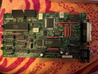
IMG_4917.jpg
 
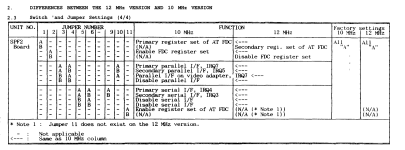
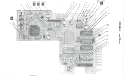
Just google Epson SPF2 and you'll get a pile of information.
View attachment 1258419
Thank you very much for this information. I think I need to change my search engine on my browser. It had zip on this product.

I need to ask you a couple of question regarding tracks per inch or TPI. I am working on a machine that sets up either floppy speed or floppy density by TPI. So what in this case is TPI? Is it speed or density of the tracks on the floppy disk?

The machine I am working with has floppy A set to 96-TPI and floppy B set to 48-TPI. B didn't exist when I received the machine. The machine is AT&T 6300 Plus 286 6-MHz with what appears to be a 1.2-MB floppy. The problem I have is that the spindle and the head assembly don't seem to move when the machine boots. The display states for Floppy as Not Ready. I have checked the power for the floppy and both the 12-V and 5-V sources are present. I have tried to change the drive to 360-KB, another 1.2-MB and 1.44-MB 3.5 inch drive with same results. I tried changing the TPI on the motherboard in hopes to find the right combination with no success there as well. In addition, I learned the 1.44-MB has a TPI of 135 and don't know how that is handled in an old machine like this one. The controller is built into the motherboard and is a NEC uPD765AC floppy on a chip controller. I thought if I introduced a ROM driven floppy controller then I might be able to get the machine to boot. I have a Sam's Photofact for this machine that has some BASIC programs to test the floppy system. But, if I can't get the machine to boot then the BASIC programs are useless. Suggestions?
 
You can check out a floppy drive with just the power connected using nothing more than a test probe.
Use the "Shugart" pinout here. All signals are active-low, so that grounding any pin asserts a "true" level. Do note that all odd-numbered pins are grounded.

For example, so see if the drive spindle motor works, ground pin 16 on the drive. The motor should come on. Since the standard cabling for PC-type floppies is all drives use the second drive select, the drive "active" LED should come on when pin 12 is grounded. If you keep pin 12 grounded, you can step the carriage by grounding pin 20, with direction determined by pin 18. And so on.

Floppy drives are basically dumb devices and not difficult to check for operation.
Okay, I'll do this test today. I'll let you know results. Thank you!!!
 
I watched the boot process of the 6300 Plus and everything passes except the Floppy where the floppy head and spindle doesn't move. The system states No Floppy and displays Primary boot strap followed by the same line except with the added line Disk Read Error. In addition the lamp on the floppy is continuously Red and lighted.

So, first I took Pin 16 from the floppy to ground. Nothing happened that is the drive motor didn't budge following a power off/on again to get a clean reboot.. So, I tried grounding the other pins like 18, 20 etc and no response as well. These were tried over multiple reboots.

I then tried the Epson SPF2 and that was a no go as well. I read through that chart provided by Chuck(G) and realized at the Epson is dependent on the floppy drive controller (FDC) from the AT motherboard and not with a built in ROM. If the 6300 Plus FDC is hosed up then the Epson isn't going to work anyway. I tried it anyway and the lamp on the floppy drive came on as soon as power was applied and stayed on displaying the same response Primary boot strap and Primary boot strap Disk Read Error.

I thought about using a GoTek since it doesn't require motor activity. Thoughts?
 
I suspect that you're counting the pins wrong or there's a power issue. Grounding pin 16 on any 3.5" or 5.25" 34-pin drive results in the motor spinning.
 
I suspect that you're counting the pins wrong or there's a power issue. Grounding pin 16 on any 3.5" or 5.25" 34-pin drive results in the motor spinning.
Well let me explain to you how I grounded the individual pins to the 1.2-MB floppy. The floppy drive itself has edge surface connectors. There is no way to touch those edge surface connectors since the ribbon connector edge covers the entire surface connector. The ribbon cable I used has both edge connectors and 34-piin connectors as well. I have a set of 90 degree wire connectors that I plugged into even pins. I checked the odd pins and found that you were right about those to be grounded. Counting from right to left to the physical 16th pin; I connected an alligator clip wire to the 16th pin to ground and then powered on the computer. Result was no reaction from the floppy. Could the reverse little endian be a factor here; if you recall the 6300 had a reverse little endian? I wonder if the same is found with this 6300 plus? Maybe I am reading the pins incorrectly.
 
Note that I said "connect the power only; forget about the signal connector. Looking at the edge connector, the top pins are numbered 2,4,6,8,10,12,14,16...just the way shown in the diagram from pinouts.ru. The bottom pins are numbered 1,,3,5,7.... So, ground (you can use one of the power grounds (i.e. the center two pins in the Molex power connector) the 8th pin on the even side of the edge connector.

Note that "top" and "bottom" may be reversed, depending on the drive manufacturer. You can usually locate the 1/2 side of the edge connector by the "slot" cut in the edge connector thus:
0226465880228.png
 
Okay, since the focus is for power to be delivered to the drive and no signal connection. I can use the ribbon female edge connector as access to the drive without the signal cable being connected to the computer motherboard. Using your diagram above I should be able to see if the jump to ground of the suggested pins to see action from the drive.
 
1686001301702.png

The enclosed picture is of the floppy drive control board. When I ground pin 16 the chip Q1 shown in the picture gets very hot to the touch. So I did something wrong, obviously. My plan now is to change out the power supply and look for a 1.2-MB floppy drive since I think this one is toast.
 
A summary:

The a fore mentioned procedure shown in earlier discussions on the floppy not booting were helpful but not a solution. After trying the method that Chuck(G) suggested, I realized that I had inadvertently knocked out the Toshiba floppy drive that came with the computer when purchased. I bought a 1.2 MB TEAC drive to replace the damaged Toshiba and when installed discovered that the TEAC would boot from a MSDOS diskette, but only once. I’ll explain more below.

First, I made discovery that was having an effect on the AT&T 6300 Plus machine. I removed the AT&T 6300 Plus and replaced it with my AT&T 6300 to allow me to boot from floppy to correct a batch file on the hard drive. I used the AT&T monitor and the AT&T 302 keyboard from the Plus. When I booted the 6300 the same error that occurred from the Plus was now occurring in the 6300. I knew that the 6300 was fully operational and found that a profound error was propagated from the Plus by some means. The only changes were the hard drive RLL card and the keyboard. I found the error was occurring in the AT&T 302 keyboard. I exchanged the 302 keyboard for a AT&T 301 keyboard and everything returned to normal including booting from floppy. I went back to the 6300 Plus and the result was the single boot of the aforementioned TEAC floppy drive.

I changed the configuration on the machine following the boot, to include a 1.44 floppy as B drive leaving the TEAC 1.2 Floppy as A drive. This change, even though hard switched from the DIP switches for two floppies on the motherboard, was not recognized and failed to boot once again. This where I discovered that there is one or more PAL chip’s that act like CMOS found on 386 models. A Sam’s Photofact that I have on the machine shows a daughter board on the machine, which is directly involved with the floppy drive system according to the Photofact.

Documentation in the Photofact writes about a setup disk, which came with the original machine upon sale of the machine. Trixter has a AT&T 6300 Plus similar to my machine. We discussed the existence of a setup disk. Both Trixter and I don’t have this disk and using web sources the disk couldn’t be found unless I find another owner who might have this setup disk. Trixter believes that the disk is unnecessary, however, in lieu of the errors encountered with my 6300 Plus; I believe that setup disk, however primitive, may be needed to invoke a configuration in the small PAL that must exist on this 286 AT&T 6300 Plus machine. Right now I can boot from the hard drive.

When I purchased the machine, I believe the received configuration of a hard drive and floppy on this AT&T 6300 Plus may have programmed into a PAL chip found on a daughter board. I would hate to say that this is the only configuration that is recognized by this machine. Sam’s Photofact shows a number of points on the daughter card for testing where with an o’scope visually see if the frequency and amplitude. Testing the components of the daughter card will be difficult as the components are face down towards the motherboard. I think this is the next step in solving this mystery.
 
Back
Top