Elladur
New Member
Hi all,

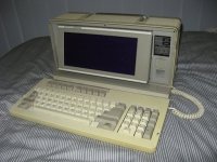
I've had this PC-7100 in my collection from before I knew I was collecting, I found it on the way home from school in around 1998-99. Sadly a few years back I discovered that the built-in 20MB hard drive was starting to fail. I thought being an MFM/RLL style drive that it would be very tricky or near impossible to find a replacement and figured it was now a display piece rather than a running machine.
A couple of months ago I stumbled onto the XT-IDE series of boards, after a bit of research and the disassembly of the PC-7100 I discovered that the hard drive is actually a Plus brand "HardCard 20". The HardCard plugs into what looks like a standard ISA slot that is plugged into the mainboard of the PC-7100 via a ribbon cable. I purchased a Lo-Tech CF ISA adapter kit and proceeded to build it but until now haven't had a chance to try it out.
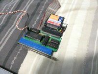
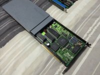
Here are a few pictures of the HardCard 20 and the Lo-Tech CF ISA card plugged into the "ISA" riser card (for lack of a better term?).


Finally I had some time that I could sit down and work on installing the card, I spent a few hours yesterday fiddling around with the machine with no luck. I got in touch with James at Lo-Tech and described my problem and after a few emails he recommended that starting a post on here would be the best approach! So here I am
After a few emails it looked like the problem was with the "ISA" slot, while it may contain signals from an ISA bus it doesn't have every signal connected through. After buzzing out which pins were connected I had the list below:
I can only imagine that there is some decoding logic on the mainboard coupled with the address lines configured the way they are that allow this card to behave normally.
This is the part where I throw my hands in the air and ask for help! I need to get stuck in and read up on how the addressing works for this card in a normal system and wrap my head around how this works in the PC-7100 configured the way that it is. Any help or pointers here would be great, I'm hopeful that with some jumpers to patch around the messy addressing I'll be able to get my PC-7100 back up and running
Ross

I've had this PC-7100 in my collection from before I knew I was collecting, I found it on the way home from school in around 1998-99. Sadly a few years back I discovered that the built-in 20MB hard drive was starting to fail. I thought being an MFM/RLL style drive that it would be very tricky or near impossible to find a replacement and figured it was now a display piece rather than a running machine.
A couple of months ago I stumbled onto the XT-IDE series of boards, after a bit of research and the disassembly of the PC-7100 I discovered that the hard drive is actually a Plus brand "HardCard 20". The HardCard plugs into what looks like a standard ISA slot that is plugged into the mainboard of the PC-7100 via a ribbon cable. I purchased a Lo-Tech CF ISA adapter kit and proceeded to build it but until now haven't had a chance to try it out.
Here are a few pictures of the HardCard 20 and the Lo-Tech CF ISA card plugged into the "ISA" riser card (for lack of a better term?).


Finally I had some time that I could sit down and work on installing the card, I spent a few hours yesterday fiddling around with the machine with no luck. I got in touch with James at Lo-Tech and described my problem and after a few emails he recommended that starting a post on here would be the best approach! So here I am
After a few emails it looked like the problem was with the "ISA" slot, while it may contain signals from an ISA bus it doesn't have every signal connected through. After buzzing out which pins were connected I had the list below:
Code:
01 - GND       02 - GND
03 - D7        04 - RESET
05 - D6        06 - A01
07 - D5        08 - D4
09 - D3        10 - D2
11 - D1        12 - D0
13 - +5V       14 - +5V
15 - AEN       16 - A0
17 - IOR       18 - IOW
19 - DRQ3      20 - DACK3
21 - Note#1    22 - Note#2
23 - Note#2    24 - Note#2
25 - +12V      26 - +12V

Note#1 - A5, A8 and A9 are tied together on this pin

Note#2 - A2, A3, A4, A6, A7, and A10 through A19 are tied together on this pin and connected to GND
I can only imagine that there is some decoding logic on the mainboard coupled with the address lines configured the way they are that allow this card to behave normally.
This is the part where I throw my hands in the air and ask for help! I need to get stuck in and read up on how the addressing works for this card in a normal system and wrap my head around how this works in the PC-7100 configured the way that it is. Any help or pointers here would be great, I'm hopeful that with some jumpers to patch around the messy addressing I'll be able to get my PC-7100 back up and running
Ross
