I'm not following. Would a modern router/hub/switch work for any kind of in-house signal, even a 2400 baud modem call?
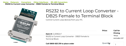
Direct message sent. At the very least I want to find out what these are and do.
This is the same sort of thing that the X10 1980s home automation stuff ran on, right? (See
LGR's video for demonstration.) I can't say I've considered it, and I really don't want to try to rely on the electrical network of my house to send signals. Not because I think it would be unsafe, but my network is pretty cobbled together, with some walls of some rooms being on one circuit, other walls in the same room being on a different one, and at least two outlets that are double-fed. I had an electrician last month put a weather box on my outdoor front outlet, and he got shocked because the ground wire there was actually energized! They had to send a more skilled electrician on a second visit to solve that little puzzle.
Wood frame house with plaster walls, with an attic and a crawlspace. Built in 1959 with an addition in 1972.
After looking at pictures of what a 66 block is, no way do I want to do that much individual wiring!

I'd much rather just stick with whole cables and ports. Plus, I want each line to have 8 wires for any future repurposing.
View attachment 1244479
Thanks. After having you explain it out like you did, this patch panel method is
definitely better than my example--much more flexible and sensible. I think my laundry room would be the best place, especially since the circuit breaker box is there as well, and the outside telephone box is on the other side of the outer wall as well. So that means the laundry room panel would be the hub, and there would be 4 lines (iterating from my example) going from there to each of the 5 rooms (a total of 4*5=20 Ethernet cables in the walls). I would control what is connected to what simply by patching at the laundry room panel.