Hugo Holden
Veteran Member
I bought a dynamic PET board on ebay. It was cosmetically clean looking, which is what I like because, normally, I can fix the hardware issues. Call this board mobo B. But this one had a very odd fault, perhaps better called a "borderline condition".
I got it as a spare for the PET computer I have.
I had already cloned all of the ROMs in my working PET call the board in this PET mobo A.
I had the ROM set sitting there and they were all tested and known to work in this PET computer.
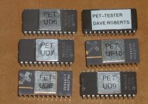
Most of them were the TMS2532 types, because these work as drop in replacements for the 6332 ROMs and they are easy to program with the readily available & cheap GQ-4x programmer.
Except for the Edit ROM and the Character ROM types, these are replaced with a 2716 UV eprom , which is also easy to program in the GQ-4x programmer too.
Therefore, I had a good set of ROM's that I had verified in my working pet computer.
I put mobo B into my PET computer to test it and repair it and this is where the fun began.
I will explain the sequence of events:
Mobo B was malfunctioning. So I inspected the power supply voltages. Initially I found that one of the blue 10uF 25V Tant capacitors filtering the +12V line had shorted out. I replaced all of the blue 10uF 25V tants on the pcb.
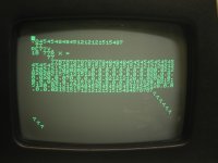
After that, as is often the case, with faulty PETs, there was a scrambled screen of characters appeared on the CRT This is the "PET thing" when many things go wrong.
I decided a smart move would be to replace all the ROM's with the duplicate set. The rationale would be; if that cured it, I could simply re-fit the old ones, one at a time, until the fault re-appeared (the best laid plans of Mice & Men in this case).
When I did this, the signs changed. Now, when the computer booted, the screen was blank. Though by turning up the VDU's brightness control, the scanning raster was there, indicating normal H and V drive pulses.
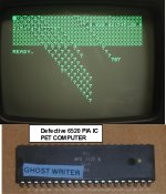
I thought, hmm.... what to do next ? So I started removing the PIA's because its easy as they are also in sockets. As soon as I removed UC7 (the keyboard PIA). Immediately the computer booted to BASIC, but without the cursor. This appears to be normal that if UC7 is not present the cursor vanishes. Later it turned out that both the BASIC 2 ROMs which came on Mobo B were faulty (corrupted) and required replacing and the edit ROM was the wrong type. So the dead parts count at this point was two BASIC ROMs, one PIA and one capacitor. Not bad for a board of this age.
Luckily i had some spare 6520 PIA's on hand (courtesy of my longstanding spare parts disease) I had bought these as spares for my AIM 65 computer.
The cursor re-appeared with a replacement UC7, 6520 PIA, and the computer started running normally....... except for a very odd fault, see attached video link, showing the screen data bouncing around vertically. The display bounced vertically for some seconds immediately after turn on (computer power up), and every time any keyboard key was pressed. But after some minutes this fault completely cleared.
After some time, I determined that if I replaced the 2716 Character ROM I had made, with the original Mos Character ROM, the problem vanished. So, as an experiment, I fitted the 2716 character ROM to the known good mobo A, and found that it worked perfectly in mobo A.
Therefore, I had a situation where the 2716 character ROM, was causing some sort of problem in mobo B and not mobo A. And it was a marginal condition, in that after 10 to 15 minutes after turn on, the problem vanished. What could it be that made mobo B different from mobo A ? But more to the point, how could some quality of the character ROM cause the unusual vertical instability seen on the VDU ?
Luckily, I had been doing some previous research on the /INIT line in the computer. And I had also found, that due to the design of the 9" PET VDU, the slightest disturbance in the timing or amplitude of the Vertical drive signal to the VDU results in a small series of characteristic damped oscillations in the vertical scan. (These can also be readily seen if the V height control is adjusted in the VDU). It is because of a positive feedback loop in the VDU's vertical scan amplifiers, just below the threshold to cause continuous oscillations.
In any case I figured that there was a disturbance in the V drive signal to the VDU, to cause the vertical bouncing (seen in the video)
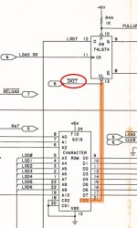
Initially I confirmed that the 2716 character ROM was causing a disturbance in the /INIT line. It turns out that pin 21 ( CS3) of the character ROM UF10 is not tied directly high, but tied to the /INIT line, which is pulled high by a 1K resistor. Somehow it (the 2716 ROM) was either injecting a transient onto this /INIT line or altering it in some way. On testing, much to my surprise I found that the /INIT line, with the original MOS Character rom sits at close to the 5V rail. With the 2716 though, at least the IC's I have, the /INIT line is dragged down to just under 2 volts, making the INIT line vulnerable to transients. This results in disturbances of the clock pulses to the CPU and the state machine that generates the V drive pulses. This causes the vertical bouncing.
I confirmed this was the case, by shorting out the 1k pullup resistor after the computer had started. Also by an experiment, disconnecting pin 21 of UF10 and tying it directly high, which also cured the problem.
Then I got to wondering about the 1k pullup resistor. I paralleled a 33k resistor with it, reducing the value just a tad to around 970 Ohms, the problem vanished. That is how marginal it was, easily explaining why the 2716 ROM could work apparently normally in one pcb mobo A but not in mobo B. However an experiment shows that when the 2716 is in position UF10, to get the /INIT line, to close to +3V requires that the 1k pullup resistor is changed to a 390 Ohm.
Pin 21 on a 2716 is the Vpp programming voltage input. In read mode it it supposed to be tied to + 5V. However, when it is tied via the 1k pullup resistor it appears capable of dragging the voltage down below 2V.
I found the simplest thing to do on the PET mobo was to merely change the 1k Pullup resistor to on the / INIT line to 820 Ohms and this fixes this unusual problem when the Character ROM is replaced with a 2716. It would be better though to simply wire pin 21 to +5V but that would mean cutting a pcb track that I am not fond of.
Probably it would have been better if Commodore tied pin 21 of UF10 to +5V and not /INIT. For example, no problems occur using the 2716 in the Edit ROM position of UD8, in that case they tied pin 21 directly to +5v.
So, this is a cautionary tale about using a substitute 2716 ROM for the character ROM UF10. It may work fine in some boards, not in others and it pays to check if it (the particular 2716) drags down the voltage on the /INIT line, easily checked with the meter.
I got it as a spare for the PET computer I have.
I had already cloned all of the ROMs in my working PET call the board in this PET mobo A.
I had the ROM set sitting there and they were all tested and known to work in this PET computer.
Most of them were the TMS2532 types, because these work as drop in replacements for the 6332 ROMs and they are easy to program with the readily available & cheap GQ-4x programmer.
Except for the Edit ROM and the Character ROM types, these are replaced with a 2716 UV eprom , which is also easy to program in the GQ-4x programmer too.
Therefore, I had a good set of ROM's that I had verified in my working pet computer.
I put mobo B into my PET computer to test it and repair it and this is where the fun began.
I will explain the sequence of events:
Mobo B was malfunctioning. So I inspected the power supply voltages. Initially I found that one of the blue 10uF 25V Tant capacitors filtering the +12V line had shorted out. I replaced all of the blue 10uF 25V tants on the pcb.
After that, as is often the case, with faulty PETs, there was a scrambled screen of characters appeared on the CRT This is the "PET thing" when many things go wrong.
I decided a smart move would be to replace all the ROM's with the duplicate set. The rationale would be; if that cured it, I could simply re-fit the old ones, one at a time, until the fault re-appeared (the best laid plans of Mice & Men in this case).
When I did this, the signs changed. Now, when the computer booted, the screen was blank. Though by turning up the VDU's brightness control, the scanning raster was there, indicating normal H and V drive pulses.
I thought, hmm.... what to do next ? So I started removing the PIA's because its easy as they are also in sockets. As soon as I removed UC7 (the keyboard PIA). Immediately the computer booted to BASIC, but without the cursor. This appears to be normal that if UC7 is not present the cursor vanishes. Later it turned out that both the BASIC 2 ROMs which came on Mobo B were faulty (corrupted) and required replacing and the edit ROM was the wrong type. So the dead parts count at this point was two BASIC ROMs, one PIA and one capacitor. Not bad for a board of this age.
Luckily i had some spare 6520 PIA's on hand (courtesy of my longstanding spare parts disease) I had bought these as spares for my AIM 65 computer.
The cursor re-appeared with a replacement UC7, 6520 PIA, and the computer started running normally....... except for a very odd fault, see attached video link, showing the screen data bouncing around vertically. The display bounced vertically for some seconds immediately after turn on (computer power up), and every time any keyboard key was pressed. But after some minutes this fault completely cleared.
After some time, I determined that if I replaced the 2716 Character ROM I had made, with the original Mos Character ROM, the problem vanished. So, as an experiment, I fitted the 2716 character ROM to the known good mobo A, and found that it worked perfectly in mobo A.
Therefore, I had a situation where the 2716 character ROM, was causing some sort of problem in mobo B and not mobo A. And it was a marginal condition, in that after 10 to 15 minutes after turn on, the problem vanished. What could it be that made mobo B different from mobo A ? But more to the point, how could some quality of the character ROM cause the unusual vertical instability seen on the VDU ?
Luckily, I had been doing some previous research on the /INIT line in the computer. And I had also found, that due to the design of the 9" PET VDU, the slightest disturbance in the timing or amplitude of the Vertical drive signal to the VDU results in a small series of characteristic damped oscillations in the vertical scan. (These can also be readily seen if the V height control is adjusted in the VDU). It is because of a positive feedback loop in the VDU's vertical scan amplifiers, just below the threshold to cause continuous oscillations.
In any case I figured that there was a disturbance in the V drive signal to the VDU, to cause the vertical bouncing (seen in the video)
Initially I confirmed that the 2716 character ROM was causing a disturbance in the /INIT line. It turns out that pin 21 ( CS3) of the character ROM UF10 is not tied directly high, but tied to the /INIT line, which is pulled high by a 1K resistor. Somehow it (the 2716 ROM) was either injecting a transient onto this /INIT line or altering it in some way. On testing, much to my surprise I found that the /INIT line, with the original MOS Character rom sits at close to the 5V rail. With the 2716 though, at least the IC's I have, the /INIT line is dragged down to just under 2 volts, making the INIT line vulnerable to transients. This results in disturbances of the clock pulses to the CPU and the state machine that generates the V drive pulses. This causes the vertical bouncing.
I confirmed this was the case, by shorting out the 1k pullup resistor after the computer had started. Also by an experiment, disconnecting pin 21 of UF10 and tying it directly high, which also cured the problem.
Then I got to wondering about the 1k pullup resistor. I paralleled a 33k resistor with it, reducing the value just a tad to around 970 Ohms, the problem vanished. That is how marginal it was, easily explaining why the 2716 ROM could work apparently normally in one pcb mobo A but not in mobo B. However an experiment shows that when the 2716 is in position UF10, to get the /INIT line, to close to +3V requires that the 1k pullup resistor is changed to a 390 Ohm.
Pin 21 on a 2716 is the Vpp programming voltage input. In read mode it it supposed to be tied to + 5V. However, when it is tied via the 1k pullup resistor it appears capable of dragging the voltage down below 2V.
I found the simplest thing to do on the PET mobo was to merely change the 1k Pullup resistor to on the / INIT line to 820 Ohms and this fixes this unusual problem when the Character ROM is replaced with a 2716. It would be better though to simply wire pin 21 to +5V but that would mean cutting a pcb track that I am not fond of.
Probably it would have been better if Commodore tied pin 21 of UF10 to +5V and not /INIT. For example, no problems occur using the 2716 in the Edit ROM position of UD8, in that case they tied pin 21 directly to +5v.
So, this is a cautionary tale about using a substitute 2716 ROM for the character ROM UF10. It may work fine in some boards, not in others and it pays to check if it (the particular 2716) drags down the voltage on the /INIT line, easily checked with the meter.
Attachments
Last edited: