• Please review our updated Terms and Rules here

VECTREX WITH PROBLEMS

Desperado

Veteran Member
Joined
Nov 25, 2017
Messages
6,827
Good evening guys,
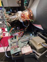
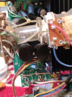
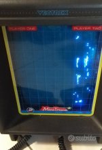
I'm about to buy a vectrex console that has a defect in the screen (as in the photo)...
do you think it can be repaired? It appears that the image is shifted all the way to the right and is compressed ...
Thanks so much!
 

Attachments

  • 8cd8ca79-0116-46b4-a967-7740d668d3ea.jpeg
    8cd8ca79-0116-46b4-a967-7740d668d3ea.jpeg
    57.4 KB · Views: 23
It probably can be repaired--there's an image. As to what the exact problem might be--it could be something as simple as a bad pot, or considerably more involve.
 
The service manual for the Vectrex (including the schematics) can be found here: https://console5.com/techwiki/images/a/a7/Vectrex-Service_Manual.pdf.

As per the PET, there is a logic board and a CRT driver board.

The first thing is to check out the power supply voltages. The analogue output from the logic board uses + and - 5V. It is unlikely that the -5V is faulty (as the y-axis appears to be working OK). But it is always the correct place to start.

If you use your oscilloscope probe on the X and Y outputs from the logic board to the CRT driver board - and you observe the signals swinging from +5V (ish) to -5V (ish) for both directions, the problem is with the CRT driver board.

On the CRT driver board, the circuitry for the X and Y deflectors are virtually identical - so you should be able to compare the waveforms at each stage through the deflector circuits to see where things go wrong.

Dave
Hi Daver!! You're expert also for Vecterex?? Wow!! Great!
Thanks so much!
 
It's just another computer...

It has exactly the same subsystems as other machines (apart from the vector video output stage - and this is similar to the Tektronix 4051 (but without the storage tube)).

The same process generally applies for all types of microprocessor computer repair...

Dave
 
Good morning! Vectrex is arrived this morning, now I start to open the console ...
 
Xmas present Opened :(
 

Attachments

  • 1.jpg
    1.jpg
    98.6 KB · Views: 20
  • 2.jpg
    2.jpg
    144.6 KB · Views: 19
Most of it appears to be working apart from the horizontal deflection system (X-axis).

Download the service manual I pointed you to in post #4 and see if you can identify the power supplies and the X-axis drive point from the digital to analogue converter to the horizontal deflection amplifier.

According to the service manual there is a plug and socket for this.

Dave
Is this?
 

Attachments

  • Schermata 2022-01-22 alle 16.19.38.png
    Schermata 2022-01-22 alle 16.19.38.png
    90.8 KB · Views: 3
no sorry...is this:
 

Attachments

  • Schermata 2022-01-22 alle 16.25.09.png
    Schermata 2022-01-22 alle 16.25.09.png
    196.4 KB · Views: 3
Nope, this:

1642865836307.png

You should be able to see the connector I was talking about (J301), the Y-AXIS drive (which is OK), and the X-AXIS drive (which is not OK).

These two signals are sourced via two resistors from the output of two operational amplifiers.

Of course, your Vectrex board may be a different revision to the service manual - and therefore have different component references, so this is the first thing to ascertain (whether the service manual is correct to your particular board set).

Putting your oscilloscope probe on IC303 pin 1 (Y-AXIS = OK) and IC303 pin 14 (X-AXIS = not OK) will give us some idea what is going on. On the working signal (pin 1) you should observe a signal varying between approximately +/-5V or so. Compare this with the non working signal (pin 14) and see what you are getting.

If you are observing a similar voltage swing on both pins (both + and -) then the problem is further down the chain. If one pin is always + (or -) the problem is round about where you are probing.

Dave
 
Thanks Dave!
I scope Pin1 and Pin14 on Ic303, i maked two little videos:

and

 
So those were interesting. Not quite what I was expecting though.

So let's get a bit more objective data before we jump to any conclusions.

Have you found the main schematic in the service manual that I chopped out that section from?

If so, can you measure the DC voltage (with your multimeter) across C326 and C327 (both 0.1uF 50V capacitors) or the nearest convenient point. If one of these potentiometers has failed, this could account for your issue.

Dave
 
Dave, this board doesn't have C326 and C327..... i have two empty spaces....
 

Attachments

  • Schermata 2022-01-22 alle 17.47.46.jpg
    Schermata 2022-01-22 alle 17.47.46.jpg
    106.1 KB · Views: 8
Can be this Dac ic bad?
 

Attachments

  • Schermata 2022-01-22 alle 19.36.24.png
    Schermata 2022-01-22 alle 19.36.24.png
    336.1 KB · Views: 6
Back
Top