It doesn't look too bad, but then I've always been suspicious of the duty cycle of a simple inverter-based crystal oscillator.
I'd suspected duty cycle too but I thought as the CMOS z80 will go from DC->8MHz it should be ok, anyway I don't now think its duty cycle...more later
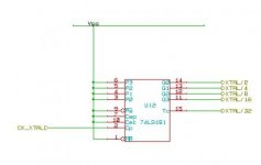
When I've had to use one, I've always made it for 2x or 4x the frequency needed and then used a high-speed flip flop (e.g. 74AS74 if we wanted to be period-authentic) to generate a clock with a 50% duty cycle. ( I note that you have a clock divider notated, but not included on the schematic.) I'd also buffer the off-board clock separately from the clock used to feed on-board logic.
The divider is a simple 4 bit counter, to give /2, /4, /8, /16 and /32 clock rates for testing. 2..16 are 50% duty whereas /32 is a carry out so has odd characteristic of 1:32 duty cycle.
Good point, I'll buffer the off board clock line through a spare '244 line.
I also know nothing of your layout, so take everything I've said with a couple kilos of sodium chloride.
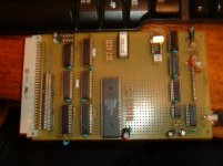
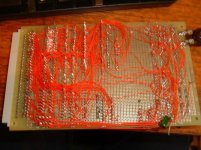
Its pretty hairy wirewrap. See attached pictures, though it works nice and reliably at 4MHz on the NMOS part....
What's your decoupling situation?
Each chip has a 100nf ceramic decoupler soldered to the power pins, the CPU in addition has a 100uF electrolytic cap (though that made no difference to current problems).
I've also tried various power supplies. At the moment the whole thing is running of a large "Farnell" Linear power supply - not sure of its output rating but at a guess looking at the circuit I'd say at least 5A and this only draws <500mA when the LED board is disabled.
...
First, a CRO on the xtal oscillator will help determine if it is a square wave. I used to use those osc circuits built around nand gates, but Andrew Lynch of N8VEM fame has got me to really like the osc modules
http://www.futurlec.com/ICCrystalsOscillators.shtml Use a 14 pin socket and you can drop in different modules easily.
The only scope I've got is pretty useless, it shows huge spikes and ringing but I've no idea whether its the scope or the circuit! I'll try and get a better scope!
...
Would you be interested in joining the N8VEM group?
I've joined and am watching, but I'd already started in on this project. I really want to design my own thing this time round though hope to join in later, I'm aiming to add a bus adapter at some point so I can plug in your cards though...
...
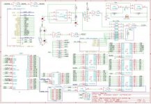
Is it possible to post the entire schematic and also a photo of the board?
Addit: I just thought of another thing - the other gates on U9 - are they floating or used somewhere else?
I'll post updated schematics to my blog later but the only bit missing from the CPU board is the clock divider
All the gates that are unused are tied to 5V, not marked on the updated schema is that I used the last NAND left as a buffer but it made no difference...
I changed the circuit last night to try and get and improvement in how the buffering works as using /WR for both the input and output buffers means that they "fight" during the transition period. I now use /RD or /M1 to enable input instead.
This made no difference to running at 4MHz the NMOS part is now ok but the CMOS part is still no go.
However it will run, albeit very unreliably with random crashes, at 6MHz now or at 2 or 3MHz - curiousor and curioser!
I'm beginning to suspect the clock now is putting out noise or some such as the CMOS part will not work at all at any speed if any of the clock or divided clock lines is being scoped (even the low speed ones when running at another low speed).
So far I've avoided "modules" for clocks as I like to build as much as I can myself and understand what is going on, but I agree now that I may have to bite the bullet and actually buy something! Though I would still like to track down the actual problem...
Cheers
Dom
") and tried a few more things out.
and tried a few more things out.