• Please review our updated Terms and Rules here

IBM 5150 showing 601 error after POST

alejack12001

Experienced Member
Joined
Jul 26, 2020
Messages
425
Location
Fredericksburg, VA
I have been trying to standup an IBM 5150 and have experienced some difficulty with the system. I was able to correct errors that I made with regard to the rocker switches on the motherboard. Once I got the memory corrected, I noticed an error preceding the machines default to the cassette boot page. There is an error displayed before the page “The IBM Personal Computer Basic” showing 601. Found this error to be associated with the floppy controller or the floppy cable or the disk drives themselves. The floppy controller is an IBM model with the edge connector which requires a cable that has edge connectors for the controller and drives. I had to modify a 34-pin dual inline ribbon cable to accommodate the needed edge connector (please see https://forum.vcfed.org/index.php?threads/substitute-lpt-for-monitor-on-ibm-5150.1241083/ post 16 for picture of the cable). I think the cable may be working, however, I believe the problem may be the configuration of the disk drives. The drives don't illuminate so it may be the cable.

In the drawing shown below there is a note that addresses jumpers for 1-4 floppy drives either beginning with DS0 or DS1.
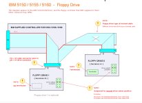
Drawing Floppy connectivty.jpg
I guess that IBM used a different type of jumper, which involves a socket with a wire straddled across the socket as seen in the attached picture of the floppy drives. A drive is terminated and shows the boot disk and located near the edge of the case while B drive is the non-terminated drive near the center of the case. According to the drawing, the jumper in question is supposed to be straddled across the second position as shown or following the note to be across first position? I don't know which is right. is that position the same for both drives? I need some clarification.
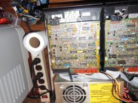
A & B Drive.JPG
 
Were the drives in the system when you got it? If so I wouldn’t think they are configured wrong, especially since they are both configured the same.

You mentioned moving the dip switches. I had a 5160 that had a 601 error. It went away when I toggled the switches for the number of floppy drives installed. I think maybe it wasn’t making a good contact. But also since you’ve been working on the switches for your other issue, maybe you bumped on of these by mistake? Should be 7 off, 8 on.
 
Point of origin for A drive came with an IBM 5162 that I got last summer. The B drive came from eBay about two months ago. Now, we all know that eBay seller's can prove that their products work or at least they say so. The 5162 had a CMOS problem and eventually I had to replace the motherboard and tested A drive and it worked there as a single drive.
 
I need some clarification.
No doubt, the POST is now trying to test the A: drive because the applicable switch on SW1 is now in the OFF position.

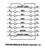
Your two TM100-2's are jumpered properly for the IBM 5150; only one wire (shunt) on the shunt socket. That only wire connects pins 3 and 14 in order to use the second drive-select option.

1671141896994.png
 
Note that no floppy is required in the A: drive. The POST's (very crude) test of A: does NOT include looking for a floppy.

Some technical detail on the 601 test is in step 29 at [here].

I list possible causes of the 601 error at [here].
 
The drives don't illuminate so it may be the cable.
The POST of the IBM 5150 only tests drive A:
And I suggest that for now, you disconnect drive B: in case of some sort of interference.

Re the aforementioned wire (shunt) on A:

1. Because of a possible bad connection, try removing then inserting that wire (shunt) a few times.

2. With a multimeter measuring the DC voltage on the wire (shunt), expect a logic HIGH (i.e. between 2.7V and 5V) leading up to the 601 test, then during the 601 test, expect a logic LOW (i.e. between 0V and 0.4V).
Seeing that ?
 
And since you can boot to Cassette BASIC, note the 'TURN ON DRIVE's LED AND SPINDLE MOTOR' section at [here].
That may be handy during the diagnosis.

And what result (a number) do you get when using the 'CRUDE REGISTER' section?
 
According to the drawing, the jumper in question is supposed to be straddled across the second position as shown or following the note to be across first position? I don't know which is right. is that position the same for both drives? I need some clarification.
Given that the Tandon TM100-2 is very common in the IBM 5150 and IBM 5160, I have added the TM100-2's drive-select configuration as an example in the diagram:

 
You mentioned moving the dip switches. I had a 5160 that had a 601 error. It went away when I toggled the switches for the number of floppy drives installed. I think maybe it wasn’t making a good contact. But also since you’ve been working on the switches for your other issue, maybe you bumped on of these by mistake? Should be 7 off, 8 on.
In the IBM 5160, things are different to the IBM 5150.

Not only is there different behaviour for switch 1 in block SW1, but in the later BIOS', the 1986 dated ones, the POST does extra stuff during 601 time. See note 17 at the bottom of [here]. I bet that your 5160 motherboard has/had a 1986 dated BIOS. Subroutine DSKETTE_SETUP would have erred when attempting to access floppy drives that didn't exist, resulting in a 601 error.
 
Thank you for pointing that out, I don’t know why I thought this was about 5160. I blame being distracted at work :)

You are correct, the XT was a 1986 model.
 
No doubt, the POST is now trying to test the A: drive because the applicable switch on SW1 is now in the OFF position.

Your two TM100-2's are jumpered properly for the IBM 5150; only one wire (shunt) on the shunt socket. That only wire connects pins 3 and 14 in order to use the second drive-select option.

View attachment 1250167
This explaination is what was being desired to explain the DS0\DS1 use. In addition thanks for the voltages seen during and following POST. I needed that as well.
 
In the IBM 5160, things are different to the IBM 5150.

Not only is there different behaviour for switch 1 in block SW1, but in the later BIOS', the 1986 dated ones, the POST does extra stuff during 601 time. See note 17 at the bottom of [here]. I bet that your 5160 motherboard has/had a 1986 dated BIOS. Subroutine DSKETTE_SETUP would have erred when attempting to access floppy drives that didn't exist, resulting in a 601 error.
I plan to follow your input today to see what is occurring during POST including the voltages suggested. I'll try it with one drive or maybe subsitute a half height drive that I have and plan to try another ribbon cable.
 
My 5162, purchased from a Boca Raton IBM employee, came with a 1.2MB HD 5.25" drive. If yours is the same, and not a DSDD drive, that might be one cause of issues.
Both of my floppy's are Tandon TM-100-2A, which I believe are 360-KB only.

If you recall, I had a lot of trouble with that IBM 5162 (see https://forum.vcfed.org/index.php?threads/seeking-utility-disk-for-modified-ibm-xt-286.1238164/) for forum help. It works now, however, I had to do a lot of modification to it to get it to work.
 
Found it. The floppy cable is bad. I used an old short ribbon cable that I had to connect between the floppy controller and one of the drives. After POST the LED of the drive illuminated and the machine read the boot disk. So, the floppy cable I was using is not right. I need to get another cable that has the edge connectors for the two floppies and the controller. I'll have make my own as finding these edge connector ribbon cables are not as prevelent as they used to be.
 
Last edited:
With the correction to the floppy cable, I was able to get my IBM 5150 to boot. Many thanks to Trixter, Modem 7 and Taco Bell Labs for your help. In addition, I got the B drive to read but not write. The error message that I am receiving is saying write protect error when I try to format a blank 360 KB floppy disk. The noch is not covered on the disk and in fact the floppy disk is a new disk. Could this be a a head issue or what?
 
On the full height drive you should be able to see the micro switch for the mechanism that enables or disables the write protect. It’s a little easier to see from the top on a tandon, and from the front on a MPI drive. Make sure that it’s not stuck up or blocked by something.

 
I guess since you mentioned the floppy cable, a problem on pin 24 might cause an issue too, but I’m not sure if a bad connection would cause write protect all the time or write enable all the time.
 
Back
Top