daver2
10k Member
Why the glum face. That accounts for why the -13V doesn't work - the circuitry is not being fed with a source of AC volts!
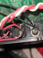
Right, so follow the RED wire back from point EP106. It should go to a switch (SW301). This should be the same for the RED wire from EP104 also.
The two wires from the transformer feed into this switch and the two red wires from the switch feed the power board.
We have two possible faults:
1. The transformer winding is faulty.
2. One of the internal poles of switch SW301 is faulty.
We need to ascertain which one...
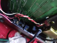
Put your multimeter black probe on the white transformer wire at EP105. Set for AC volts.
Check ALL of the power leads (both from the transformer and to the power board) on switch SW301 with your multimeter's red probe.
10V AC is good. No voltage is bad.
I am a little confused as to why you were reading -5V on the logic board though if there is no AC voltage on EP106?
Dave
Right, so follow the RED wire back from point EP106. It should go to a switch (SW301). This should be the same for the RED wire from EP104 also.
The two wires from the transformer feed into this switch and the two red wires from the switch feed the power board.
We have two possible faults:
1. The transformer winding is faulty.
2. One of the internal poles of switch SW301 is faulty.
We need to ascertain which one...
Put your multimeter black probe on the white transformer wire at EP105. Set for AC volts.
Check ALL of the power leads (both from the transformer and to the power board) on switch SW301 with your multimeter's red probe.
10V AC is good. No voltage is bad.
I am a little confused as to why you were reading -5V on the logic board though if there is no AC voltage on EP106?
Dave