• Please review our updated Terms and Rules here

c64 power supply monitor

rebeltaz

Experienced Member
Joined
Nov 9, 2008
Messages
195
Location
Shelby, AL
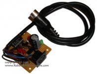
After frying three C64s because of power supplies going bad, I decided enough was enough. I designed and built a circuit that goes between the power supply and the computer. If the 5vdc line drops below 4.5 volts or goes above 5.5 volts, or if the 9vac drops out completely, then a relay disconnects the power supply from the computer to prevent any damage.

Since, from what I've learned on here, this is a common problem with C64 supplies, I thought maybe others might be interested in the circuit as well. I was thinking about selling units on eBay, but I'm not sure what it would be worth. I figured I could also sell the schematic and PCB pattern (which I designed and laid out in Eagle CAD, a free electronic CAD software program) for maybe five or ten dollars.

What do you guys think? Is there a market for this device?

The picture here is the unit I built for myself. I like the open-air design, personally, but if I sell it, I will of course build it into a project box and I will also add a bypass switch to bypass the monitoring circuit if so desired.
 

Attachments

  • c64-monitorS.jpg
    c64-monitorS.jpg
    30.5 KB · Views: 1
Home-made C= hardware is a hard sell. A very targeted market for hobbyists but not too many others. It's something I may buy, but that's me. Most owners are likely to try to build their own (I guess I would fit in that category as well). Good luck with any venture though!
 
Hm, isn't there greater damage to be had if the power supply spikes much higher voltages than expected? I don't know how often a good power supply suddenly gives up, and to what extent it will fry the computer. Perhaps you should ask the question in a more Commodore centered community. If your circuit is valuable and non-trivial, I'm sure you can sell it in small numbers. PCB layouts usually are nothing people pay to get, however ready-made items you could sell. On the other hand you could consider posting the layout for free, then offer to sell pre-etched boards or manufactured units. But before you do that, ensure your circuit will break at too high voltages as well.
 
Hi
I'm not sure a relay will drop fast enough to protect
well. Most overvoltage protectionj systems use
what they call a crowbar. It is an SCR that
sorts the output, long enough to blow a fuse.
These crowbar circuits react in less than a usec
while a relay takes a couple millisec to release.
Dwight
 
He has a great point.

The bad part is that unless you fuse the adapter board to be slightly smaller than the C64 power supply's fuse then you'll blow the fuse in the supply.

Granted, that's a good thing if you blow the fuse on the C64's power brick since it'll protect your system, but if you blow a couple out then people may wonder if the protection device is broken or not. ;)

Raymond
 
Crowbar

Crowbar

How about combining the two ideas ?
Since the SCR( once triggered ) will stay on until the power is gone( or the polarity changes ), the fuse is going to blow.
Why not rig up the circuit so that you're passing the current through some transistors, and when your conditions are met, the transistors turn off ? That way, you still have a quick response time, but you're not blowing fuses. The current isn't that heavy that you'd need real big ones. You'd get about a 0.2 V drop across the collector-emitter junction, but that might not be that big of a problem.

Or, you could just replace the regulator with a 7805 & small heatsink and be done with it.

patscc
 
I appreciate all of the responses.

patscc --> I'm switching both the ac and the dc lines, so I don't think running the power signals through transistors will work. As for replacing the regulator with an 7805, the power supply bricks I'm dealing with are sealed in epoxy. Not very conducive to repairs. The supply I'm using now is the Microline I got. It has two 7805s in parallel. I know not a good design, but I didn't design it. Still I trust it more than I do the OEM supplies.

channelmaniac --> I didn't know the power supply bricks had internal fuses. I would have thought if that were the case, then this circuit wouldn't even be necessary. BTW - thank you for the link to the circuit board fabricators.

dwight --> The crowbar is a good idea and the response time is a good point. I'm wondering if maybe solid state relays would be quicker. But then, and I am not that familiar with them, but will they pass ac, or are the just big optocouplers?


carlsson --> The 5 volt line is protected against higher voltages. I have the acceptable range set to 4.5v to 5.5v, but that can easily be adjusted using the two trimmer pots. I didn't test the 9vac line for high voltage because that wasn't one of the complaints I've seen in this forum about these supplies. Aside from that, I thought this was a Commodore-centered community? I'm sure there are several people here who would take offense at that comment ;)
 
9vac

9vac

You'd probably be okay with a relay for the AC. Asides from the expansion port, 9V unregulated go to the cassette motor, and the +12 V that's derived from the 9VAC via a 7812 goes primarily to the SID. By the time the 9VAC would rise fast enough to blow out the the 7812, which would be your first line of defense against frying the SID, you relay would have opened up, so you could use the transistor for the +5 VDC line and the relay for the 9VAC. Or, if you just want to stick with the relay, you could maybe hang a largish cap and a 5.6 V zener in there to absorb any surges while the relay is still dis-engaging.
patscc
 
Or, if you just want to stick with the relay, you could maybe hang a largish cap and a 5.6 V zener in there to absorb any surges while the relay is still dis-engaging.
patscc

Now that I like. I added the zener to the output tonight and, with a variable power supply, quickly ran the voltage up to over 12 volts. The zener did it's job and clamped the voltage to no higher than 5.6 volts - I was using a 5.1v zener with a 10 ohm resistor, so I was happy with the results. I did decide to leave the cap out though, since that tended to bleed the voltage down slowly, which would defeat the whole purpose of the under-voltage protection offered by the circuit.

Thanks for the suggestions....
 
This sounds/looks a lot like one of the gizmos I unboxed yesterday (I started a new "Help Me Identify These Things Please So I Can Sell Them" :) thread yesterday but it hasn't been made public yet [not sure what the hold up is]).

http://www.onemanband.com/eBay/C64/MiscStuff.JPG

(the blue box in the upper-right)

It says Pat. Pending, so you might want to be careful Derek.

-- Bob
 
I'll be damned. Hmmm... I don't know how they did it, but if my design is different, I would think I should be ok. I may not even try to sell it, though...

That is cool, though. Thanks for that picture.
 
I may not even try to sell it, though...
If you do produce units for sale, make yourself 101% certain they work and protect what you intend to. You do not want unhappy customers who bought a device to protect their computers from power spikes, just to find a spike got through and zapped the chips anyway.
 
Ya, that's my thought. There's a big difference between making a DIY design and posting it vs. making something proprietary and for profit. People's expectations are completely different, and you have to consider liability - especially since this is a safety device dealing with power supplies.

Even if you publish the schematic and PCB layout as a DIY project, many people would probably be willing to buy one from you, or at least a blank PCB, but at least you can cover yourself by saying "use at your own risk". I.e. you are selling the convenience of making the project for people, not a product.
 
Yeah, you're both right. I may do that (release it as a DIY) after I'm sure it's working correctly...
 
Back
Top