• Please review our updated Terms and Rules here

My first attempt at PET Repair. Model 4016. Advice Welcome!

To Kevin: It only takes one line of BASIC to run this sum check on a PET as Mike proved to me. You then just compare the answer with Mike's approved list of ROM sum checks.

Here is a BASIC program which will check the modulo 256 sum check of a ROM in the 9000H (UD12) socket. There are more clever ways to do this, but this one is a little more understandable:

Code:
10 address = 9*4096 rem base address of 9000H ROM slot in PET
20 for i = 0 to 4095 rem use 2047 for E000 editor ROM!
30 let dat% = peek(address + i)
40 let sc% = sc% + dat%
50 if sc% >= 256 then let sc% = sc% -256 rem modulo 256 sumcheck
60 next i
70 print "sum check = " sc%
 
Unsoldering UD6 from the 4016 and putting it into the 8032 will be my next step. Can you give me the line of BASIC I need to type for the sum check? EDIT: Got it, we must have been posting at the same time!

Ok, now I understand the tube comment! What I meant was that my 8032 is in excellent shape, but has really bad screen burn. So for a complete restore, I need a new tube. That hasn't been a priority, but something I'd like to do eventually.

I just looked up the NOP Generator, it I agree it is quite simple. If I get to that point, I might need some help interpreting signals though.
 
Last edited:
Kevin,
The sum check of the BASIC 4 kernal ROM (901465-22) is 25 decimal. You can check the number right away on your working 8032 by using a base address of 15*4096.
-Dave
 
Here is a BASIC program which will check the modulo 256 sum check of a ROM in the 9000H (UD12) socket. There are more clever ways to do this, but this one is a little more understandable:

Code:
10 address = 9*4096 rem base address of 9000H ROM slot in PET
20 for i = 0 to 4095 rem use 2047 for E000 editor ROM!
30 let dat% = peek(address + i)
40 let sc% = sc% + dat%
50 if sc% => 256 then let sc% = sc% -256 rem modulo 256 sumcheck
60 next i
70 print "sum check = " sc%
Ouch, I had forgotten how long it takes to run this on a PET.
Anders and Mike provided faster and shorter versions (these still take quite a few seconds):
Code:
10 for i= 9*4096 to i + 4095
20 s = s + peek (i)
30 next i
40 print " Sumcheck = " s - int(s/256) * 256
 
It will be late tonight before I am able to get to it.

I also have an EPROM programmer if it's any benefit, but it's only a few years old, so it probably won't do these old chips.
 
I also have an EPROM programmer if it's any benefit, but it's only a few years old, so it probably won't do these old chips.

The part you need to program, to be pin-for-pin with the ROM used in the universal PET boards, is the Texas Instruments TMS2532. The access time rating does not matter, as anything with a 450 nS or faster will do. National Semiconductor also made a compatible 2532 EPROM. They need a programming voltage (Vpp) of 25V so most modern EPROM/EEPROM programmers do not handle it. You can find the spec sheet for the 2532 at this link.

The 6540 ROMs used in the older PETs do not have an equivilent EPROM so an adapter must be used with them.

I can provide you with any programmed 2532 you may need gratis as you are saving a Commodore PET.
 
Ok, pulled UD6 P/N 901465-22 out of my 4016 and placed in socket UD12 on my 8032. Actually, I put it in a machine-tooled socket first, because the socket pins make better contact in those old PET sockets. Then ran the 2nd batch of code you gave me:

10 for i= 9*4096 to i + 4095
20 s = s + peek (i)
30 next i
40 print " Sumcheck = " s - int(s/256) * 256

Result: Sumcheck = 25

Is that what was expected?

EDIT: I just realized that UD6 is socketed in the 8032. Put the ROM from the 4016 into UD6 socket in the 8032, and it boots fine.
 
Last edited:
Result: Sumcheck = 25

Is that what was expected?

Yes, 25 decimal. The F ROM is good. Now that you have a socket in place, you might want to run the RAM diagnostic EPROM that has been developed by one of the guys here. It was developed for the old PETs that do not use the 6545 CRT controller, so we may have to add the initialization routine for the 6545 in the code. E where are you?

Also the NOP Generator would tell us if the address signal paths are OK. This is the most complicated part of a PET.
 
...the RAM diagnostic EPROM that has been developed by one of the guys here ... was developed for the old PETs that do not use the 6545 CRT controller, so we may have to add the initialization routine for the 6545 in the code. E where are you?
I wonder if it wouldn't be fairly simple to just make it beep, sort of like a PC's POST beeps, and avoid (or in addition to) the CRTC initialization...

@ Kevin: why not do a checksum on the socketed E ROM (UD7) while you're at it.

BTW, the reason I asked about the CRT is that I'll probably be scrapping some old terminals which may well have compatible tubes; don't really know how I'd safely pack and ship it though if you were interested.
 
Last edited:
Ouch, I had forgotten how long it takes to run this on a PET.
Anders and Mike provided faster and shorter versions (these still take quite a few seconds):
Code:
10 for i= 9*4096 to i + 4095
20 s = s + peek (i)
30 next i
40 print " Sumcheck = " s - int(s/256) * 256
Dave, I'm curious: since we're doing this in BASIC, why the MOD256? Wouldn't it actually be better (and easier) to show the actual total? BTW, is that list of checksums accessible anywhere?
 
I wonder if it wouldn't be fairly simple to just make it beep, sort of like a PC's POST beeps, and avoid (or in addition to) the CRTC initialization...

@ Kevin: why not do a checksum on the socketed E ROM (UD7) while you're at it.

BTW, the reason I asked about the CRT is that I'll probably be scrapping some old terminals which may well have compatible tubes; don't really know how I'd safely pack and ship it though if you were interested.

Hi guys...I managed to squeeze in that test of UD7 quick before work this morning.
UD7 Sumcheck=128.

As far as the tube, I appreciate that. First, let me check at my office and see if we still have any. My company used to sell refurbished terminals, and we used to stock 3 or 4 different kinds of tubes. That has been a few years ago now, and I'm pretty sure they got rid of that old stuff, but it might be worth a look. I have to be in the office all day today, so I will poke around.

I am unable to put any serious time into this for the next few days as we have family visiting (last night I had to make an excuse about having some work to finish up) but let me know if you want me to try something and I will see if I can squeeze it in. I'd like to replace those old white ROM sockets, because they have such poor connections.

This is great fun, by the way. Thanks guys for all your continued help.

Kevin
 
Dave, I'm curious: since we're doing this in BASIC, why the MOD256? Wouldn't it actually be better (and easier) to show the actual total? BTW, is that list of checksums accessible anywhere?

Mike, yes, now that I think about it, you are right. But I guess we are just using the tradition of most ASCII data formats like Intel Hex.

Anyway here is a file of the data you gathered for most of the PET ROMs:

View attachment ROM sumcheck.txt
 
It's a handy little tool, either a spare 6502 or a 'shim' socket to go between the 6502 and its socket, that has the data lines disconnected from the main board and permanently wired so that the CPU sees a NOP code; it will then perpetually cycle through all the addresses and you can probe all the ROMs, RAMs, buffers etc. with a scope looking for shorts, bad sockets, etc. They're very regular and distinctive signals, each address line half the frequency of the next lower one.

See here for instructions (in German, but pretty clear if you translate):
http://home.germany.net/nils.eilers/nopgen.htm

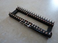
Ok, I just got some time to pick at this. I made the NOP Generator, now if I can just figure out what to do with it!
P1020485.jpg

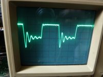
I poked my scope probe around on UD6, and the address lines did exactly what you said. Each address line was half the previous one, with a nice clean signal. However, I was wondering what you're supposed to see on the data lines? I got this on all the data lines, measured from UD6:

P1020487.jpg
 
Well, the main purpose of the NOP generator is to let you check the address lines on each chip connected to the bus, in order to find bad sockets, bad drivers, RAM/ROM chips pulling down the signal, etc., and also the decoded addresses selecting the various memory and I/O chips (CS or CE).

The data lines won't be that meaningful; the signal you show is kinda interesting with that ringing signal higher than the rest, but the scope settings would be helpful. I assume it's 2V/div with 0 offset at the 2V level? What's the time base?

Nicely done, BTW.
 
Last edited:
Well, the main purpose of the NOP generator is to let you check the address lines on each chip connected to the bus, in order to find bad sockets, bad drivers, RAM/ROM chips pulling down the signal, etc., and also the decoded addresses selecting the various memory and I/O chips (CS or CE).

The data lines won't be that meaningful; the signal you show is kinda interesting with that ringing signal higher than the rest, but the scope settings would be helpful. I assume it's 2V/div with 0 offset at the 2V level? What's the time base?

Nicely done, BTW.

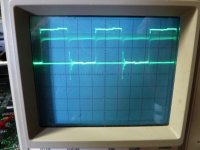
Thanks. Time base on the scope on that pic I sent was .5uS, I think, and yes it was 2v, 0 offset. I'm not sophisticated enough to know exactly what it is I'm looking for, but just that on the address lines I had a nice square wave, and on the data lines I had this flashing stuff that I had to ask what it was. I also managed to look at the CS line (pin 20) on all the ROMs just now, and there is definitely a negative going pulse on all of them every second perhaps more often than that.
 
Ok, I went back and went through the address lines on all the ROMs, and I was not able to discern a difference from ROM to ROM. I was wondering why it would be, since those lines are all connected together...but then I remembered something from my deep dark days in school where a short will become more evident the closer you get to it. Anyway, I couldn't see any difference on all the address lines.

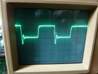
Then I got thinking about that ring...look at the clock signal right on pin 37 of the CPU. As I said, I have practically zero experience troubleshooting digital circuits, but that doesn't seem right.

P1020489.jpg
 
Sometimes all you can do is serve as an example of others of what NOT to do! :eek:

The ringing was ringing in my head, and suddenly it dawned on me. I was using a substandard scope probe with little chip clips on the ends, and I suddenly had a revelation: I had clipped on an additional 3 foot DVM probe to give me a proper pointed end to probe with. Took that out, and instead of 5vpp on that ring, I get 3vpp. I bet if I get myself a proper scope probe, it will be reduced even further! I am learning....

P1020490.jpg
 
I also managed to look at the CS line (pin 20) on all the ROMs just now, and there is definitely a negative going pulse on all of them every second perhaps more often than that.

This is very good news. It means all the chip selects for the ROMs are working fine. There should be a negative going pulse for 4096 instruction times out of every 65536 instruction times as each ROM contains 4096 addresses and the entire address space of the 6502 CPU is 65536. Each NOP instructions takes 2 microseconds so the frequency of the pulses is actually about 7.6 Hz (1 pulse every 131,072 microseconds).

So far everything we checked in your PET is working i.e, UD6 and UD7 ROMs, address decoder logic and by inference, the CPU chip.

What to tackle next, guys? RAM or the big I/O chips? Unfortunately they are probably all soldered-in parts.

-Dave
 
I was thinking of the big I/O chips. Would it boot without the 6520s? One is socketed, and as I said earlier, I'm way more confident about my soldering than my digital logic troubleshooting. Can I pull these to eliminate them?

EDIT: I decided to go for it. I removed UB12, UB15, and UB16, one at a time. Just checking for a beep or anything on the screen at this point. Still nothing. At least those chips will be socketed.
 
Last edited:
Back
Top