• Please review our updated Terms and Rules here

PDP-11/44 Restoration

I had a Tex 453 back in the seventies, it was old back then! Think that scope came out in the late sixties. Good to see that there is still one alive. Anyway looking at the picture it looks like you may be in the 0.1V/m scale and if that’s the case that’s only around 0.2 vpp and with switching supplies they often generate wide band noise that appears to be everywhere so sounds stupid but with the scope ground connected to the same point try touching the scope probe to the chassis or ground and see how much wide band noise you still see? If you were using the X10 probe that’s another story and you may have week output filters in the power supply. If the breaker is not tripping when you turn the thing on and off imagine maybe it’s good and I am just being paranoid but in my line of work I repair high powered broadcast transmitters and replace AC circuit breakers all the time so am unusually suspicious of them. Know what you mean about the weight, my 11/34 has to be the heaviest computer I have ever worked with. Got any pictures of your system?
 
Thanks. And I can't quite make it out, but it looks like your vertical v/div is at 0.5 v, right, and you're seeing spikes that stretch from top to bottom on the screen.
patscc
 
Patscc, the 'scope is set at 0.1v/div, and the time base is set at 10us. The spikes are present, but they are very faint. When we determine if it is safe to turn on again, I am going to take a better picture of the trace so you can analyze it better.

Qbus, I am unsure if the probe is an X10, but the probe says:
P6006 BNC 9
10X ≈ 11pf 10Mohm

The probe does not have the ground alligator clip on it so that could also cause some problems. I have some other probes that I can use that have 1x and 10x switches, the small adjustment knob on them, and the alligator clip. I can make a measurement using one of those probes. I think that the probe I used is the one that originally came with the 'scope.

Another point to make about the 'scope. I had the ground connection from the front panel connected to an earth ground that was common with the power distribution box. I did not have it connected to the chassis ground of the PSU. I have sinced changed the 'scope's ground to the PSU's chassis. I know that bad grounding can cause 'scopes to act funny.

Stand by for the pictures.
 
Think the Tek 465 was the first Tektronix that had auto probe stuff, little lights that show you what scale you’re on or something like that. The newer stuff incorporated it into the on screen display but the Tek 453 was like Tektronix first all solid state high bandwidth high performance scope and it was too primitive to incorporate that. Don’t get me wrong I am not dissing your bottle because back when it was introduced it gave you the power and capability of one of those huge old vacuum tube scopes like a 545 or 547 in one third the size and weight but when the 465 hit the market everyone dumped their old 453 and 454 scopes. That’s why I am amazed to see someone still using an old 453 In comparison to the PDP-11/44 that scope is a good ten or twelve years older.
 
Yeah. I love my scope. I don't really have the need to use it very often, but it is very helpful for the basic stuff I use it for. The other thing I like about it was that it was designed to be repaired. Every single transistor in that thing is in a socket, not soldered in.

Patscc, that was a great tutorial. Thanks.

A quick question about the breaker I forgot to ask earlier. What kind of lube should I get for it?
 
Good question. I need to dig out a breaker I can drill open to figure out how to get something in there, and while I'm doing that I'm hoping inspiration will strike.
How far are you from a RatShack, by the way ?
patscc
 
I assume that you mean Radio Shack. If so I am not too far away from one, but it's selection in regard to components and related stuff is pretty pitiful.

The way I got the cleaner in the breaker is through the small gap between the switch and the housing. There are also four small holes near a cover on the back of the breaker. The cover cannot be removed, I have tried. Do you think that that would work for the lube. I don't want you to have to ruin a breaker.
 
I have a box of spare breakers somewhere that I have no real use for, so I'm all for drilling one apart in a worth-while cause. See if they have something called tuner cleaner( should say cleans and lubricates on it somewhere ). I'll look up part numbers tonight. No use going there and asking them.
patscc
 
Okay. Thanks for the help with that. Another piece of info that may be helpful is that there are some slots on the tops of the breakers that seem to connect to the inside. What do you think of that?

Currently all of the switches are making contact. Right now I am just going to leave the switch in the on position so I don't have to spray the cleaner on them again.
 
I have all of those things. For the desoldering tool, I have a desoldering iron. Is that okay? I might have some desoldering wick lying around.
 
I got the contact lubricant and I sprayed the breaker. It seems to work fairly reliably now. I still have to tap the one switch, but the lube probably needs time to work itself into the components.

Now that that is taken care of what should I do?

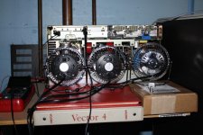
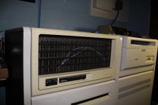
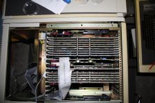
Here are some pictures of the system:
IMG_0986.jpg
The test setup for the PSU
IMG_0987.jpg
There is another RK07, but it is hidden
IMG_0990.jpg

If it's too risky I won't try this idea, but maybe I could see if the power controller's relay deactivates when the PSU shuts down. If it is an over temperature condition a signal should be sent to the controller to deactivate the relay.
 
Last edited:
Let's start by connecting the +5 remote sense to the +5 rail.
If you could do some more measurements. We're looking at the logic inverter control module.
There's a PWM chip, a 3524 on there. You should measure about 2.5 VDC with a DMM on pin 2. With a scope, you should be able to see a 30kHz signal on pin 14. It should be between 0.5 and 4 V P-P (peak-to-peak)
On pin 16, you should see 5 VDC. On pin 15, you should see 12 VDC, with minimal AC.
Before you power it on, do a dry run( or two ) to make sure you can quickly move from test point to test point.

Not having it in front of me, if it's difficult or impossible because the board's installed, post back and I might have a fix for that.
patscc
 
Last edited:
I will probably need to make an extender cable so I can have the logic inverter out of the case for the test points. So it might be too hard, but not impossible.

For the +5v remote sence do I connect the backpane to the PSU?

Thanks for finding these test points. I don't think that I would have been able to find them on my own.
 
Shouldn't have to connect it to the backplane, just connect it to the +5v output. Before you build a harness, though, you might want to double-check the components on the output board, that's the three 15000uF caps C1,C2,C3, the diodes D1,D2,D3,D4, and the snubber board. Don't worry about testing the SCR Q1.
patscc
 
Okay. To be on the safe side should I remove all of the cards from the backpane?

Besides the simple short test is there any other way that I can check those caps? I believe that the ratings on those are beyond my multimeter's capacitor check function.
 
Last edited:
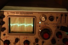
As part of the process of getting ready to do the tests, I thought I would make a quick check with the scope again with a 1x probe. I think there is much more ripple than I realized.
IMG_0991.jpg

http://www.retrocmp.com/tools/pdp11gui/memory/37-how-tos/decnet/61-reparing-a-h7140-power-supply

This person's troubles with the PSU are completely different than mine, but the shut down problem is similar. He mentions that a voltage monitoring circuit cuts the power off after a while. He found that there was a lot of ripple current on the +15v line, and the crowbar circuit shut the PSU down. I bet the filter caps between ground an +5 are bad.
 
Last edited:
Back
Top