• Please review our updated Terms and Rules here

Commodore PET 2001-8 Video Problems

All of the innards, the extra board and close up of the gold chips that say 'mostek mk4215p-3' on them.

Has anyone had any luck finding a data sheet for those Mostek chips? Searching for them finds nothing but an eBay listing from someone who obviously doesn't know what they are selling them for $18 each because they're RARE and little else.

Just looking at the board, however, I second the suggestion that it's a dynamic RAM expansion. (My offhand guess being that a board using SRAMs wouldn't need so much support circuity.) Is it possible that they're 4k Dynamic chips and the board is 8k mapped after the onboard RAM, making for a 16k PET? Taking a quick look at the original-board schematic it looks like the expansion connector doesn't carry the SEL0 signal from the 74154, so unless you're running a jumper wire or otherwise hacking the mainboard an offboard solution like that can't replace the first 4k?

In any case, it should be safe to remove it and set it aside.
Yes, it's probably a memory expansion, but AFAIK the MK4215 is a tri-voltage 16k x 1 DRAM chip like the 4116, so that would make it 32K; presumably an 8k section or the on board RAM is disabled.

Instead of closeups of RAM chips, pictures of the manuals, rear panel etc., how about wiping off some of the dust and telling us who the manufacturer of that board is (I can make out the COPYRIGHT 1978 but not by whom); give us something to work with...

And where do the cables go, especially the one marked F1?

And the numbers on the ROM chips as I had asked? Does one of them have the numbers scraped off?
 
Last edited:
Yes, it's probably a memory expansion, but AFAIK the MK4215 is a tri-voltage 16k x 1 DRAM chip like the 4116, so that would make it 32K; presumably an 8k section or the on board RAM is disabled.

As Eudi mentioned, RAM address $0000 - 0FFF (4K) must be from the main board so your first option is probably correct, addressing on the expansion board starts at $1000 or $2000 selected by jumpers. Too bad this PET uses the old 6540 ROMS and 6550 RAMs which are so hard to find. If these memories are bad, perhaps a PETVet would be a good solution to fix this system.
 
As Eudi mentioned, RAM address $0000 - 0FFF (4K) must be from the main board so your first option is probably correct, addressing on the expansion board starts at $1000 or $2000 selected by jumpers.

It would be exceedingly sleazy, but if this is indeed a 32k memory board I suppose in theory it wouldn't be that hard to yank all the SRAM from the first bank on the motherboard, run a jumper (you might be able to just use one of those micro-clips to avoid having to solder) to the SEL0 line and use it to allow the memory board to replace all the RAM. (Assuming you could pull this off without making permanent changes to the expansion board itself, which is probably more collectable than the whole PET.) Of course, that's making the *big* assumption that those sexy ceramic and gold DRAMs have held up better than the 6550s.

(I tossed the 4k DRAM idea out there for conjecture, but it was a long shot. I was just having *no* luck finding a definitive cross-reference linking the mk4215 to the 4116.)

The screen corruption, of course, points to something besides RAM and ROM, though, so ordering a PETVET might be jumping the gun. Those old PETs don't need to initialize any hardware to make a "sensible" screen display. (If ROM or RAM are bad it'll be full of garbage, but it'll be legible garbage.)
 
It would be exceedingly sleazy, but if this is indeed a 32k memory board I suppose in theory it wouldn't be that hard to yank all the SRAM from the first bank on the motherboard, run a jumper (you might be able to just use one of those micro-clips to avoid having to solder) to the SEL0 line ...

No, I think this would be a great idea to save the PET if most of the 6550 RAM chips are bad. However hopefully at least 8 of the 16 chips will be good and can be installed in the lower 4K memory sockets and no cut & jumpers will be needed. We may need to run your RAM test routine in the F000 socket to find out which chips are good. Of course all of this must wait until the screen if fixed.
 
Hi All,

Thank you for all the responses, I can't say that I was able to follow it all but I am going to read up this weekend and hopefully get a basic understanding... MikeS, I was interviewing last week so I didn't fancy getting dirty but I will clean up the board some more and get those ROM chip numbers next week (As I recall though, they were MPS 6540 but I am not totally sure). The F cables connect from the PSU to the expansion board and then to the main board, I assumed that was just power but it does feed to the expansion board first. I believe the expansion board says COPYRIGHT 1978 R. C. FACTOR but I will have to check again when I am back in the office next week.

I disconnected the expansion board as suggested, I just removed the ribbon cable but left the power cables where they were as I wasn't sure about their orientation. The screen came to life! I must admit I got a little excited.

Unfortunately it just displayed random characters all over the screen. I plugged the expansion board back in (powered down) and there were still characters displayed but this time the screen wasn't full of them, just a scattering.

I have been reading some other broken pet posts and like many people have I left the pet on for a while and check for chips getting hot. They all seemed fine.

I hope that helps and I will get more information next week.

As I side note I got in contact with the company who originally supplied the PET, they have changed names a few times but still exist. I spoke to the MD who had a lot of memories of these PETs, they even supplied some to Twycross Zoo in the UK to help sort out the chimp feeding patterns.

I really appreciate you all taking the time to help.
 
I disconnected the expansion board as suggested, I just removed the ribbon cable but left the power cables where they were as I wasn't sure about their orientation.

Always take notes, make sketches, take photos before disconnecting connectors to ensure they will be reconnected correctly. Reversed connectors are the number one source of 'technician induced failure'.

Unfortunately it just displayed random characters all over the screen. I plugged the expansion board back in (powered down) and there were still characters displayed but this time the screen wasn't full of them, just a scattering.

This is a great sign that your video board (just under the CRT) is OK. Did you reseat the J7 connector that takes the video controls signals to the video board or just the expansion connector? Keep an eye out for the return of the jittering screen when the system gets warm. If it returns, this may indicate a temperature sensitive capacitor or +12V regulator in the video board.

On power up, the screen usually comes up with random characters. The PET ROM program should then attempt to clear the screen and initialize the system. something may be going wrong at that point.

You may not have an oscilloscope, but do you have a voltmeter?
-Dave
 
...I will ... get those ROM chip numbers next week (As I recall though, they were MPS 6540 but I am not totally sure).
They are generically indeed 6540s, but the contents are different in each one. There will be at least one other number (probably in the form 020 3980A or 901439-13) that will identify the specific ROM contents; this will tell us which version of BASIC, whether all ROMs are standard and, if you tell us the column number, whether each one is in its proper location. Never hurts to check the basics ;-) .

The F cables connect from the PSU to the expansion board and then to the main board, I assumed that was just power but it does feed to the expansion board first.
The rear connector does look like the original power cable coming from the off-board filter capacitor; the one marked F1 looked like it had more pins, but if it also has five pins and only goes to the original five pins on the main board then you could probably just remove the cable marked F1 and connect the cable from the capacitor directly to the main board. Dave's advice to make lots of notes and take lots of pictures is excellent advice, but as it happens the power cable in question is symmetrical and can be plugged in either way.

Do check that the connectors really make good contact; that was one of the weaknesses of the old PET, usually evidenced by charring and signs of overheating on the board around the connector.

I believe the expansion board says COPYRIGHT 1978 R. C. FACTOR but I will have to check again when I am back in the office next week.
I don't recognize it; anybody else?

I disconnected the expansion board as suggested, I just removed the ribbon cable but left the power cables where they were as I wasn't sure about their orientation. The screen came to life! I must admit I got a little excited.
Don't blame ya; sounds like good news! Looks like without the extra board we've just got the classical old PET problem, probably a bad socket or a bad ROM or RAM chip. I don't suppose there's anyone else in your part of the world with a similar PET with whom you could get together?

The usual first step is to carefully remove and replace all the socketed chips; before you actually remove them and risk bending/breaking a pin you could try just pushing them back and forth in their sockets.

Buying a PETvet as suggested would probably make it easier (as well as expanding memory and giving you some options), if that's an investment you don't mind making.

Good luck!
 
The usual first step is to carefully remove and replace all the socketed chips; before you actually remove them and risk bending/breaking a pin you could try just pushing them back and forth in their sockets.

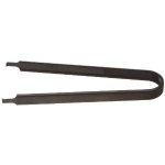
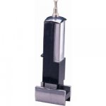
Before completely removing and re-seating the chips from the sockets as Mike suggests, if you are a novice (or ham-fisted like me), you may want to consider obtaining a removal tool and an IC insertion tool for the 0.6" wide devices (ROMs) as thirty year old IC pins are easy to bend or break off. Unfortunately the RAM chips (6550) are an oddball size and you will not find an insertion tool for them.


IC Extraction Tool ___24-28 pin IC Insertion Tool

IC extraction tool.jpg24 pin insertion tool.jpg
 
Before completely removing and re-seating the chips from the sockets as Mike suggests, if you are a novice (or ham-fisted like me), you may want to consider obtaining a removal tool and an IC insertion tool for the 0.6" wide devices (ROMs) as thirty year old IC pins are easy to bend or break off. Unfortunately the RAM chips (6550) are an oddball size and you will not find an insertion tool for them.
Good advice from Dave as usual.

Failing that, the important thing is to remove the chip vertically, i.e. without tilting it; slipping a knife blade underneath and gently and carefully rocking it up and out will usually remove it without problems. When (re)inserting, make sure all the pins are properly seated in the socket, push down gently, and before pushing all the way in double-check that none are folding under. And of course make sure the chip is facing the right way!

As I said, often just pushing the chips back and forth sideways along the long axis can clear up a bad connection temporarily.

Most of the pins are in parallel among the three groups of chips, so measuring continuity with an ohmmeter (with power off) from a pin on one chip to the same pin on another in the group will reveal any bad connections.

Here are the schematics for that board; 320008-2 shows the RAM & ROM chips and which pins are connected together:

http://www.zimmers.net/anonftp/pub/cbm/schematics/computers/pet/2001/320130-1.gif
http://www.zimmers.net/anonftp/pub/cbm/schematics/computers/pet/2001/320008-2.gif
http://www.zimmers.net/anonftp/pub/cbm/schematics/computers/pet/2001/320008-3.gif
 
Last edited:
the important thing is to remove the chip vertically, i.e. without tilting it; slipping a knife blade underneath and gently and carefully rocking it up and out will usually remove it without problems. When (re)inserting, make sure all the pins are properly seated in the socket, push down gently, and before pushing all the way in double-check that none are folding under. And of course make sure the chip is facing the right way!

Mike,
Very well written. You could have earned a living writing instruction manuals for Heathkit...

Had I read this in my youth, it would have prevented the crippling of hundreds of bugs....:)
 
Hi All,

So I finally got around to looking at the Row H chips.

Read from the left.

Chip 1 - MPS 6540 - 0260680A
Chip 2 - MPS 6540 - 2031379
Chip 3 - *** 6540 *021**** (Unfortunately the number have been rubbed/scratched off)
Chip 5 - MPS 6540 - 0250680A
Chip 6 - MOS MPS 6540 - 0241379
Chip 7 - MPS 6540 - 022137* (Last number/character is unreadable)
Chip8 - 6540 - 0201279

Row G

Chip 1 6520 - 0478
Chip 2 6502 - 4979

I haven't been able to get any of the Electronic Engineering technicians to check it with an Oscilloscope... Everyone is out for the winter break.
 
A friendly tip: when you're asking people to remotely analyze your system, check and double-check what you're describing; it can save a lot of time wasted on red herrings and possibly avoid serious damage.

There are only 7 chips, not 8 (you skipped #4), they are numbered right to left, not left to right (see the numbers across the front of the board) and I think you transposed two digits in your #2 (should be 023 1379); the first three digits identify the ROM and the last 4 digits are the week and the year that the chip was manufactured. The 6502 (in row F, not G) is the main processor.

Allowing for that, those chips are the BASIC2/3 set, so your PET has been upgraded at some point; good to know.
 
Last edited:
Back
Top