NeXT
Veteran Member
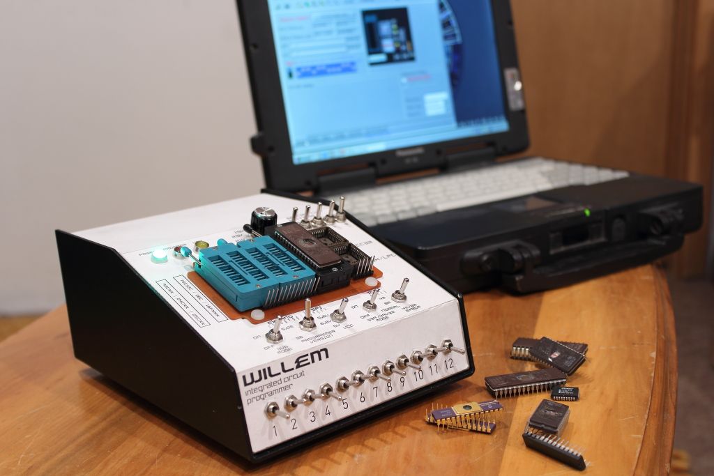
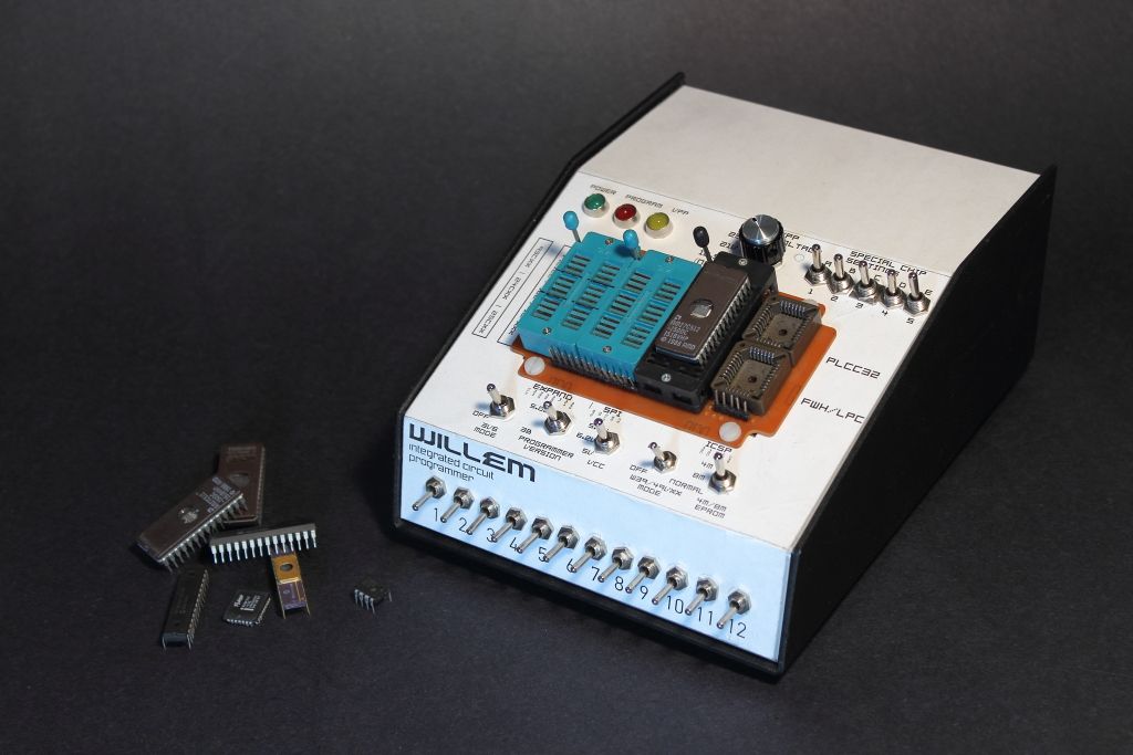
So I jsut finished my conversion of a Willem programmer from a single board to a fully enclosed unit.
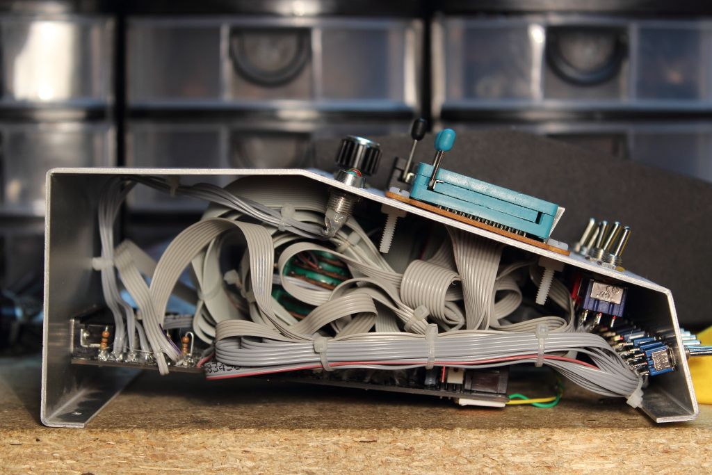
I checked and double checked my wring as I assembled it and never found any problems. I've discovered a major issue while setting up to burn a 27C512.
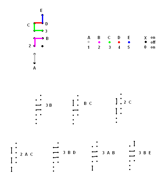
If DIP switches 1 and 3 (or 6 and 7) are both on the voltage at the green power LED jumps form 5v to 12v and the onboard regulator that takes the 12v from the wallwart and drops it to 5v overheats until the thermal cutout threshold is reached. Looking at the schematic the 12v I'm using is isolated to a very tiny region of the PCB. Looking over my work again I can't see a place where there could be a short or miswired connection. What's even more baffling is it's ONLY if switches 1 and 3 are up (or again, 6 and 7). If only one of the two are on then it doesn't happen. Just to confirm with anyone else with a Willem, this isn't the result of no chip being plugged in or the PC not being connected, right?
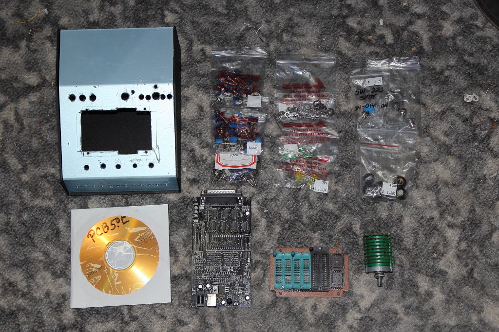
I'm based off the version 5.0e PCB originally. This is how it looked before it was stripped of all its headers.
I checked and double checked my wring as I assembled it and never found any problems. I've discovered a major issue while setting up to burn a 27C512.
If DIP switches 1 and 3 (or 6 and 7) are both on the voltage at the green power LED jumps form 5v to 12v and the onboard regulator that takes the 12v from the wallwart and drops it to 5v overheats until the thermal cutout threshold is reached. Looking at the schematic the 12v I'm using is isolated to a very tiny region of the PCB. Looking over my work again I can't see a place where there could be a short or miswired connection. What's even more baffling is it's ONLY if switches 1 and 3 are up (or again, 6 and 7). If only one of the two are on then it doesn't happen. Just to confirm with anyone else with a Willem, this isn't the result of no chip being plugged in or the PC not being connected, right?
I'm based off the version 5.0e PCB originally. This is how it looked before it was stripped of all its headers.
Last edited: