• Please review our updated Terms and Rules here

Chicklet pet displays single line only

Can anyone
recommend an inexpensive FPGA for that purpose with many IO pins?

Thomas,

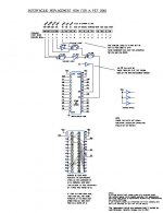
A small board called the PETVet uses an ATMEGA644 AVR chip and has done everything you need. I'd advise anyone with the old style ROMs and RAMs (6540 and 6550) on their model 2001 PETs to get one and save a lot of time trying to replace those "impossible to get" parts. See: PETVet from bitfixer.com. Mike also has a great PETDisk gadget for the IEEE bus. That is the easiest way to get PET programs from the internet into your old PET as it uses a PC compatible SD memory card. I am a happy user of these gadgets and can vouch for them.
-Dave

The only problem with Mike "Gubbish" is the delay time :D

I also have a petdisk, it's very useful!
 
The only problem with Mike "Gubbish" is the delay time :D

I also have a petdisk, it's very useful!

Giovi,
Yes, on this forum he is known as gubbish, and in real life I think he is a very busy professional software programmer. But he will reply to emails to bitfixer at his website if you are patient. It may be faster to order a kit rather than a completed tested unit. And of course, for the really ambitious, he does have the complete schematics and source code on his website.
 
Thanks for the advice. Maybe eventually I'll go for the PetVet as
well. The purpose of the FPGA was only to get a tool that allows to
replace RAM and ROM for debug purpose. I got a couple of other vintage
gadgets so this would not only be for the Pet.

Surprisingly, the ATMega644 only runs at most at 20MHz depending on
the version which seems to be fast enough to emulate the 1MHz RAM for
the Pet. My guess would have been that this is too slow.

So far I "only" found four broken RAM chips and consider to only use
my memory expansion to replace either the broken RAM or all on-board
RAM if necessary.

Other than in my initial statement, the expansion board does not
extend the memory to 50kB but only by 32kB. Did some research on those
expansion RAM chips. They only provide a single bit so in order to
make a byte, eight of them are addressed simultaneously. Each of them
allows to store 8192 bits by only 7 address lines. Obviously too
little so an address has to be written in two chunks, the first one of
7 bits, the missing six bits are written after the falling edge.

Even if not pin-compatible, are there any suggestions which RAM and
ROM chips would be electrically compatible (with the 6550)? Guess this is a
well-discussed issue.

I have a 3D printer in the office and rather than printing funny toys
I thought about printing and adapter sockets to connect to
non-compatible chips somehow.

Thomas_
 

Attachments

  • IMG00002.jpg
    IMG00002.jpg
    51.1 KB · Views: 1
Even if not pin-compatible, are there any suggestions which RAM and
ROM chips would be electrically compatible (with the 6550)? Guess this is a
well-discussed issue.

The 6550 is a 1Kx4 static RAM and with an adapter one could use the 2114 1Kx4.
The 6540 is a 2Kx8 ROM and with an adapter one could use a total of three 2732 4Kx8 EPROMs for the 2 Cxxx ROMs, the 2 Dxxx ROMs and the 2 Fxxx ROMs, and a 2716 for the E000-E7FF Editor ROM.

See schematics for the PET 2001N.
-Dave
 
Dave,

can the 2114 replace the 6550 with a simple adapter, without any modification on the pcb lines? In this case, have you any schematics of this adapter?

--Giovi

Giovi,
I looked at the PET 2001 schematic with the old 6550 RAMs and no, a 2114 cannot be used as-is. This is due to the extra chip enables that the 6550 has which are used to decode the address down to the 1K address spaces. It looks like two 74138 decoder chips will be needed to take the SEL0, A10 and A11 lines to form the 4 chip selects for the 0000-0FFF space (lower 4K space) and another to take the SEL1, A10 and A11 to form the chip selects for the upper 4K RAMs.

I could be persuaded to burn a 16V8 PAL to do the job of the two 16 pin decoders chips with one 20 pin skinny DIP part if needed. But you would still need 16 jumpers to hook up the chip selects to all the RAM chips. The modification would a little look messy.
-Dave
 
I could be persuaded to burn a 16V8 PAL to do the job of the two 16 pin decoders chips with one 20 pin skinny DIP part if needed. But you would still need 16 jumpers to hook up the chip selects to all the RAM chips. The modification would a little look messy.
-Dave

Ok, Dave, thank you. As I told before in this same thread there's an easy-to-build RAM replacement for PET 2001 that uses just two chips (6264 RAM + 7400), but I was wondering if one could simply make an adapter that would be esthetically better.

--Giovi
 
Giovi,
I looked at the PET 2001 schematic with the old 6550 RAMs and no, a 2114 cannot be used as-is. This is due to the extra chip enables that the 6550 has which are used to decode the address down to the 1K address spaces. It looks like two 74138 decoder chips will be needed to take the SEL0, A10 and A11 lines to form the 4 chip selects for the 0000-0FFF space (lower 4K space) and another to take the SEL1, A10 and A11 to form the chip selects for the upper 4K RAMs.

I could be persuaded to burn a 16V8 PAL to do the job of the two 16 pin decoders chips with one 20 pin skinny DIP part if needed. But you would still need 16 jumpers to hook up the chip selects to all the RAM chips. The modification would a little look messy.
-Dave
I dunno; replacing 6550s with 2114s would involve adding some decoding, but a passive adapter (or two) to use a 6264 should be pretty straightforward since the A0 through A11 address lines are available on every socket; I think you'd only need one jumper and a couple of diodes for A12/CE.

Now that I read Giovi's post that's probably what he's talking about if the adapter straddles the high and low RAM socket; think I'll build one, looks pretty trivial. As a matter of fact my 2001s have a 4 pin header for A12-A15 to allow using a modified one of Jim's $5.00 adapters to replace all the ROMs; could use the same 4 pin jumper cable to put 32K RAM on the RAM adapter... Tempting to plug in the soldering iron...
 
Last edited:
Dear All,

after getting to the point to obtain a picture I wanted to pick up this thread again because the basic interpreter returns "SYNTAX ERROR" on any input and I get an @-sign as cursor.

I suppose I have a problem with some ROMs so I wanted to read them and compare them to ROM-images from the net.

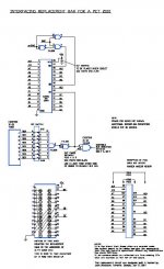
For this purpose I connected the H1 ROM to my Raspberry Pi. In order to get the content I need to supply input to all 12 address lines and read the 8 data lines. Since the RPI does not have enough general purpose IO lines I use two 8-bit output shift-registers (on the left side of the 6540 on the picture) as intermediate address memory.

The RPI sends a sequence of 16 bits to the two shift registers. Then 8+4 lines go to the 6540 ROM. The chip on the right side takes the 8 data lines from the ROM and allows to read them serially by the RPI. So from the RPI I need only one output to feed the address and one input to read the data and some additional lines to clock the chips.

Using the LEDs I was able to verify that my shift-registers contain the addresses fed by the RPI. However, the 6540 ROM does not respond in any way to the input.

After a certain address is written to the shift-registers I set the 6540 clock low and high (waiting at least 1ms) but never get any output on the data lines. For the purpose of debugging I connected the LEDs to some 6540-data lines directly to make sure my input-shift register (right hand side of image) does not cause any additional problems.

Now to the questions:

(1) It is correct that the 6540 needs a low - high clock to read an address? (I set the SEL line to GND in order to select the chip)

(2) Can you verify that my 6540 pin assigned is correct?

VSS (GND) - 1 28 - not used
VSS - 2 27 - +5V
not SEL - 3 26 - DB 0 (data)
BA 11 - 4 25 - DB 1
BA 0 - 5 24 - DB 2
BA 1 - 6 23 - DB 3
BA 2 - 7 22 - DB 4
BA 3 - 8 21 - DB 5
BA 4 - 9 20 - DB 6
BA 5 - 10 19 - DB 7
BA 9 - 11 18 - BA 10
+5V - 12 17 - +5V
BA 8 - 13 16 - clock
BA 7 - 14 15 - BA 6


(3) Another problem is that the RPI only provides 3.3V. It has a 5V power supply line but the output pins might only provide 3.3V

Thanks in advance and best regards,

Thomas
 

Attachments

  • 6540.jpg
    6540.jpg
    36.8 KB · Views: 1
Now to the questions:

(1) It is correct that the 6540 needs a low - high clock to read an address? (I set the SEL line to GND in order to select the chip)

(2) Can you verify that my 6540 pin assigned is correct?

1) Yes, and you must read the data while the clock line is high.
2) Yes, pin 4 (BA11) should always be zero

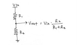
I'm not sure that a 3.3V Raspberry Pi is TTL tolerant. You can output from it to TTL but you should not read 5V signals directly into a Pi. Use a voltage divider to lower the voltage to 3.3V to the Pi input (called V out in the sketch). R2= 20K and R1 = 10K

divider.jpg
 
Last edited:
Hello Dave,

I got the idea dividing the current, thanks. I almost feel like an electrical engineer now :)

To get closer to the core of the problem I connected the ROM to a proper switching power supply today, coded a few addresses with 5V manually and measured the data lines. In fact I was able to read the same bytes repeatedly so the chip seems to basically work. The scope showed 3.6V for the output only so I decided that the RPI has to take that. With 3.3V input, the 6540 raises only to about 0.8V for high.

So I connected everything again, used the 5V from the RPI and still got nothing. After reading the shift-register's datasheet thoroughly again I realized that it has a "clear all flip-flops" line which I never used because I don't want to clear it. But of course, 'not use' is tri-state. I rather need to connect it to high or low. So after that I was able to use the four LEDs to lead the lower nipples of the bytes which were addressed by the RPI (I love those nipples :D ).

Tomorrow I'll use the input shift-register to read the bytes and tell you how it proceeds.

Thomas
 
Eventually it worked. I found out that both my H5 (C800-) and H6 (D800-) are broken. They either read FF or F8-FF values only.

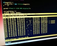
I wrote a tiny hex-dump programm which drives the Raspberry PIs GPIO ports (4 writing, 1 reading) and compares the result to a binary provided as parameter on the command line. The output is: Address / hex dump 6540 / ASCII dump / hex dump binary file with hints on differences. Feel free to use the tar archive attached. The cxx-file give some (sparse) details on wiring the RPI. The only library needed is the 'wiringPi' lib.

Now I'll have to find out how to replace the ROMs - a well-tackled issue I guess.

Thomas
 

Attachments

  • read_rom.jpg
    read_rom.jpg
    97 KB · Views: 1
  • read_rom.tgz.zip
    15.8 KB · Views: 1
That's kind Dave, thanks.

I still think about interfacing a simple system on a chip with the address and data bus and emulate the missing parts myself, particularly because three RAMs are broken as well. I know it means reinventing the petvet but would be an interesting project at the same time.

Will let you know once I got further.

Thomas
 
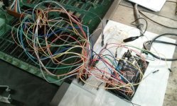
The development advanced a bit but probably into the wrong
direction. Since Dave mentioned that the PetVet from Michael Hill uses
an Arduino I bought an Arduino Mega 2560 which runs at 28MHz. My
intention was to emulate the missing ROMs and RAMs and actually right
from the beginning I was skeptical whether emulating the memory at a
speed of 1MHz would work. But since I was told the Arduino does the
job I also went for it.

Rather should have looked into Michael's documentation first because he
describes his project in detail and even released it under the GPL
(have to express my admiration of his project here!).

He does not really emulate the memory but uses a 628128 64kB RAM chip
which serves the bits. The Arduino only loads certain parts of the
memory with ROM images (I should have known, I know).

I tried with the Arduino board nevertheless. If you use the
digitalRead() and digitalWrite() function there is no chance of
serving the bus at a rate of 1MHz, each takes about 50
cycles. However, the digital pins are memory mapped and can be written
8 at a time writing a byte into addresses called PORTA, PORTB and so
on.

A single loop that only cycles a byte between 0-255 and writes it to
the port immediately allows me to create a 2MHz signal. But in order
to emulate the memory I have to read at least two ports, combine that
to an 11-bit address, get the respective byte at this address out of
the memory and write it to the 8-bit output port (see code in
image). I have my doubts that this will work at a rate of 1MHz. And
even if, I might get into aliasing problems like missing a rising
edge because a 1MHz sampling rate is not enough.

Then my current wiring does not take the chip select line into
account. If this is low I would have to set my output pins to "input"
because otherwise my data signal would overwrite the data coming from
the RAM or another ROM because it is not always my emulated ROM's
turn. In conclusion: A hopeless case.

Right from the beginning I thought that an FPGA would be a better
choice for emulating the memory as it has no internal clock and can
easily synchronize with the Pet.

I ordered the memory chip first because it will yield a quick solution
but the FPGA approach is still my long-term aim.

Regards,

Thomas
 

Attachments

  • arduino_code.jpg
    arduino_code.jpg
    35.8 KB · Views: 1
  • arduino_wiring.jpg
    arduino_wiring.jpg
    77.5 KB · Views: 1
Sounds like fun all right, but sure a lot more complicated than a couple of 6540 adapters and some jumpers...

A slightly messier but interesting approach by a local fellow PET owner (especially since he mounted it under the board to hide it):

PETram.jpgPETrom.jpg
 
Sounds like fun all right, but sure a lot more complicated than a couple of 6540 adapters and some jumpers...

A slightly messier but interesting approach by a local fellow PET owner (especially since he mounted it under the board to hide it):
Yes,
That would do it. I always liked the Nick Welte approach with the big EEPROM and a 32K byte RAM chip and a simple GAL chip together with a DIP switch to control the address mapping and selection of ROM sets.

Thomas seems to want to find a super fast controller chip with lots of internal memory to do the RAM and ROM emulation in the one chip without use of supporting external flash or RAM memory.
 
Back
Top