• Please review our updated Terms and Rules here

Replaced soldered in Ni-cad cmos battery

Billyray

Experienced Member
Joined
Apr 7, 2007
Messages
186
Location
NE Ohio
Welp, I found this replacement battery on fleabay They're brand new and sold by Radio Shack, so it's for a good cause.. ;)

I had to remove the motherboard on my mini-tower AMD 386 @ 40Mhz. The ni-cad was mounted too tight to surroundings to snip. I wasn't looking forward to ruffling the feathers on this venerable old bird. The push pins mounting the board gave me some trouble, but I had spares. Once I got the board out, I followed the usual instructions of adding a little new solder to the pin, then soaking it up with copper braid, then prying out with solder iron on each side. My battery also had the glue blob. I noticed that the battery connector (which was a four pin setup) had one dead hole to make sure you oriented it correctly. My mobo has all 4 pins on the header, unfortunately. It is also not marked what is Pos. Neg. So I tried my luck and bent down 1 of the middle pins and snipped it out. Buttoned things up and turned on. Nope. Low battery error message. Re-opened, bent down other pin and snipped. Made a note inside the case about which way the plug must go. Buttoned up again, turned on, Success!! Checked all peripherals, network, memory, Windows, programs, etc. Everything is good. I guess the old bird is tougher than I thought. I checked again after leaving off for about 20 mins. Will keep checking after a couple of days of being off. I like the fact that the Lithium has the correct original voltage, and supposedly should last for a long time.

With the ni-cad I had to be sure to turn pc on every week or so to charge it up. It was losing about 5-10 minutes every few days. Still surprising how long it lasted (21 yrs.) without leaking, and staying usable. The pc sat unused for about 13 yrs. straight in my basement before being re-discovered a year or two ago.

Very glad this job is done! Now I can worry about the capacitors instead... :wow:
 
I just drill the blanked hole in the battery connector with a small drill bit in a dremel.
 
Last edited:
The negative (black) terminal is always (in my experience) connected to the PCB ground plane, so a simple check with an ohmmeter should sort the mystery of the pins out. At least it's always worked for me.
 
This battery isn't doing too good. After just a few hours, it already lost a half hour of time. I may have to go to plan B. I have a 2 AA battery and a 3 AA battery holder that I might try next. It's too bad this new Lithium can't do as well as the old Ni-Cad which only lost a few minutes after several days. The old Ni-Cad was 3.6 V @ 50 mAh whereas the new Lithium is 3.6 V @ 2100 mAh. Maybe it's actually old.

Good idea Chuck!
 
It may seem logical to think that a battery connected to the 'external' battery connector should be the same voltage as the NiCad. But on some motherboards, the design of the electronics associated with the 'external' battery connector results in a 3.6V battery being inadequate (or borderline). We have seen this before on these forums.

[More information]

I may have to go to plan B. I have a 2 AA battery and a 3 AA battery holder that I might try next.
Try the '3 x AA' one first.
 
I think you may be barking up the wrong tree. Going by the old MC14686 CMOS clock/memory used in the 286 and copied ever since, the maximum current draw at a 32687 Hz clock rate is only 50 microamps.

I really have to wonder if you don't have a problem with the 32KHz crystal. Can you measure the frequency?
 
Maybe it's actually old.
The manufacture date is printed on it. The one in the picture says June, 2006 on it. Yours may say something else.

The one I'm currently using on my 486DX2-66 board says October, 1990 and it's still going strong. But, with batteries, you never know.

But on some motherboards, the design of the electronics associated with the 'external' battery connector results in a 3.6V battery being inadequate (or borderline).
They seem to work fine on every board I've used them on.
 
They seem to work fine on every board I've used them on.
It could be that the majority of old motherboards are okay with a 3.6V external battery, and that your motherboards fall into that majority.
The IBM 5170 motherboard is one example of a motherboard where the use of a 3.6V battery can result in the loss of time (see [here]).
 
I'll add that the board would have charged the original Ni-MH battery while "on" at higher than 1.2 V per cell. You had three cells in series, so it's charged at over 3.6 V.

if you substitute a 3.6 V lithium-metal primary cell directly it will be subject to that reverse current, which will damage it. You need to put one diode in series with the cell.

see here: http://www.vintage-computer.com/vcforum/showthread.php?44691-Check-those-batteries!
 
If I understand correctly, Paul, this is not a replacement of the NiCd rechargeable, but a primary cell attached to the "external battery" 4-pin header that's common on boards of the 386-486 era. The board does not supply charging current to those pins. I've got a few of this type of board, all with 4xAA alkaline cells that have been running for many years.
 
Thanks guys for all of the suggestions. I tried replacing the Lithium 3.6v with two button cells (2032) in a holder making about 6.4v. The problem persists. The CMOS has always been protected and saved just fine, but the RTC is actually shutting off while the pc is off. The reason I think that is because the time displayed when I turn pc on is about 2 minutes after I last shut it down. I am now wondering if one of those two middle pins on the header need to have + volts connected for the RTC. While the machine is on, keeps time perfectly.
 
Last edited:
I believe that you'll find that one of the extra pins is NC and the other is connected, as is the adjacent outer pin to power ground.

Thanks Chuck! I was leaning toward shorting a middle pin to Pos., but you were right! I shorted the ground pin to the adjacent one instead, and it appears to have worked. I have to do some more tests, but I am hoping that was all it was.

I checked the computer after being off over night, and upon turning it on, it had the exact correct time and date, so all is well.

For anyone finding this thread in the future, here are the specs:

The motherboard is a KMC A419-8 (ACER ALi M1419) 386 Cache Motherboard; see here and here. My board does not have the Dallas RTC, but rather the Motorola MC146818A here which does not have an internal battery, but is powered by the CMOS battery we are discussing.

The battery header, labeled "J4" and has pin "1" closest to the board edge like this: 4 3 2 1 |<-board edge
Short together pins 1 & 2 (ground) and pin 4 has the battery positive side.

Right now I am using 2 button cells (CR2032 or +6.4v) in a holder like this

Perhaps the 3.6v Lithium battery would have been ok, but I have not retested it.
 
Last edited:
My board does not have the Dallas RTC, but rather the Motorola MC146818A here which does not have an internal battery, but is powered by the CMOS battery we are discussing.
On these old motherboards, the use of 'internal' and 'external' battery is in relation to the motherboard:
INTERNAL = NiCad battery (normally soldered to motherboard)
EXTERNAL = Off-motherboard battery connected to 'external' battery connector

I think that whichever company started the use of 'internal' and 'external' should have used 'onboard' and 'offboard' instead.

Short together pins 1 & 2 (ground) and pin 4 has the battery positive side.
The 'normal' pinout of the external battery connector is a copy of that on the IBM 5170 motherboard:
Pin 1 = ground
Pin 2 = ground
Pin 3 = not connected
Pin 4 = +V

Pins 1 and 2 are connected together on the PCB.

You have one of the variations of the norm.
Another variation is shown on page 92 (PDF page 22) of the manual [here].
 
I thought it was odd that the pins weren't just shorted on the mobo too. :confused: Maybe it had something to do with the fact that it came with the ni-cad. But I do have more peace of mind knowing the ni-cad is gone and the computer is keeping perfect time. So there was an improvement with this mod. :D
 
Most boards often have an optional jumper to use either
a rechargeable or non-rechargeable when they have the
4 pin header.
I also never replace NICADs by soldering them to the board.
I always run about 3 feed of insulated single strand wire to
cells placed in a baggie.
I've had too many boards damaged by leaky cells.
You need to use single strand as the multi-strand will wick
the KOH to the board.
Dwight
 
Hi Guys,
I have a question related to this discussion. I have a two 486 boards which had the soldered in battery. When booting them up one day, one of them indicated the battery was dead. I opened it up to find the battery had started to leak and amazingly it somehow didn't leak onto the board but did corrode part fo the case. So after removing the board and cleaning the case, I unsoldered the battery from both motherboards (the second board was still working okay, but why chance it).

So I will replace those batteries with an external battery. Although the manual says the external battery connector is for 3.6v, I am still thinking of using a 4xAA battery holder which would be a nominal 6 volts (the actual voltage is always a little less). I have used these before on 386 boards seemingly without incident.

Am I safe to go with the four battery holder or should I go with a 3xAA holder for 4.5 volts?

Thanks...Joe
 
Hey Joe, I'll chime in that I am using the two coin cells (total of 6v) My soldered in Ni-Cad was 3.6v just like yours. I think the 4 AA batteries will work like a charm. Smart decision to replace even the good ni-cad battery. Mine was still functional too, but it WAS losing time if it sat for extended periods (like a week or two.)

New wrinkle with my battery replacement

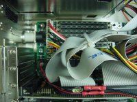
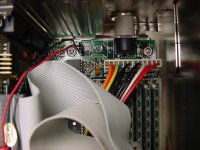
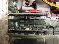
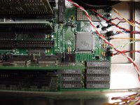
So everything is humming along since last week, when I decided to take some shots of the inside of the case for future reference. Here they are:

pats386 001.jpgpats386 005.jpgpats386 002.jpgpats386 003.jpg

Afterwards, I button her up and fire it up, and the clock is wrong again!!! AAAArggh!

First fix was to tighten stranded wire to get a better connection on the shorted pins 1 & 2 --- nope, didn't help
Second fix was to actually solder the wire shorting the two pins for a certified connection --- nope, didn't help
Third fix was to add a ground wire to the battery negative and to the case. ---Success!!

SO how was it working for the past week? Apparently, where I had twisted the stranded wire it was sticking out and touching the metal case. I noticed it and thought, that shouldn't hurt anything. I just didn't realize that it was CRUCIAL! So I am really hoping this battery project is done for good now.

If you look close at picture 2, you can see a line going to the steel slot cover. Apparently with all my jostling when taking the photos, and buttoning her up again, I lost that tiny ground touch. :whatthat:
 
Last edited:
I don't think it really matters. The CMOS clock is pretty tolerant to a wide range of voltages. I've always used 4x alkaline AA cells, because that was the battery holder typically distributed with the cases of that period. At least use alkaline cells; carbon-zinc cells have a rather short life, whether or not you're actually drawing from them. They'll last for years. And do take Dwight's advice--put them in a plastic bag or other container where the most you'll risk is the battery holder if things leak. Remember that the electrolyte in alkaline cells is bad news for zinc plating as well as any magnesium or aluminum alloys.

Some applications that demand 3.6V lithium primary cells are pretty intolerant of lower voltages. In particular, trying to replace the PRAM backup battery (3.6V) in Mac Performas with a CR2032 (3.0V) coin cell, doesn't work.
 
Last edited:
Back
Top