• Please review our updated Terms and Rules here

Programming 16L8 on NeedHam EMP-11 Programmer

The feedback, on the RWD and ONL signals is thru the 74XX11 gates.. I put on Green Paper, each signal starting with its output on the Far Right hand side and on the Left hand side was its inputs.. Doing each Output on a separate section, and I then compared them with the PAL equations on the top of page 36.. Did I miss Something..

Yes, you missed the polarity of the signal. The circuit should have fed back /RWD not RWD to get a proper latch. That is kind of important. There are quite a few other errors in the hand schematic. The good news is that the original equations you sent to me and that I posted, seem to be good when compared to the Description section of your documentation.


Actually they do.. SREW I think is the Rewind coming from a switch, while IREW comes from the Drive Controller..
Just like SONL is the switch for Online on the front of the machine.. Does, that Help ??

Yes, it means the original equation posted for REW is correct.

I will be posting the JEDEC file which passed all tests. However it is targeted for the 16L8.

Will someone out there be able to translate the JEDEC file to a GAL16V8 JEDEC that Marty is able to program? It should be targeted to the part manufacturer he is using (Lattice, National, AMD, etc.). Marty, what brand of GAL16V8 do you have?
-Dave
 
Hi All
DaveM, " Marty, what brand of GAL16V8 do you have? "" Lattice

I have two programs that supposedly will convert from PAL16L8 to GAL16V8.. PALtoGAL, PAL2GAL...

I tried to copy/scan the pages that I had made/ hand drawn, but the file size is tooo big..

THANK YOU Marty
 
Last edited:
JEDEC File

JEDEC File

Here is a link to the PAL16L8 JEDEC file called 16L8DES2.jed. Handle as a binary file as it has some embedded characters. It matches some of the files posted, but this one has some important header information like the type of PAL that was missing on others.


Here is the ASCII version of the JEDEC file for the 16L8 PAL:

Code:
PAL16L8                                    PAL DESIGN SPECIFICATION
PAL S03 DISK & TAPE EMULATOR   @ 2E  REVISION A0
S03  - TAPE STATUS @ 2E REV A0
STEVE BLIGHTMAN 10/15/86
*
QP20*
QF2048*
L0000 
11111111111111111111111111111111
11111111111011111111111111111111
11111111111111011111111111111111
11101111111111111111111111111111
00000000000000000000000000000000
00000000000000000000000000000000
00000000000000000000000000000000
00000000000000000000000000000000
11111111111111111111111111111111
11111111111111111111101111111111*
L0320 
11111110111011111111111111111111
11101110111111111111111111111111
11111010111111111111111111111111
00000000000000000000000000000000
00000000000000000000000000000000
00000000000000000000000000000000
11111111111111111111111111111111
11111111111111111111111111111110
11011111111111110111111111111111
11101111111011111111111111110111*
L0640 
11111111101011111111111111110111
00000000000000000000000000000000
00000000000000000000000000000000
00000000000000000000000000000000
11111111111111111111111111111111
11111111111111111111111101111111
11111111111110101111111111011111
11101111111111101111111111011111
11111111111011101111111111011111
00000000000000000000000000000000*
L0960 
00000000000000000000000000000000
00000000000000000000000000000000
00000000000000000000000000000000
00000000000000000000000000000000
00000000000000000000000000000000
00000000000000000000000000000000
00000000000000000000000000000000
00000000000000000000000000000000
00000000000000000000000000000000
00000000000000000000000000000000*
L1280 
00000000000000000000000000000000
00000000000000000000000000000000
00000000000000000000000000000000
00000000000000000000000000000000
00000000000000000000000000000000
00000000000000000000000000000000
00000000000000000000000000000000
00000000000000000000000000000000
00000000000000000000000000000000
00000000000000000000000000000000*
L1600 
00000000000000000000000000000000
00000000000000000000000000000000
00000000000000000000000000000000
00000000000000000000000000000000
00000000000000000000000000000000
00000000000000000000000000000000
11111111111111111111111111111111
11111111111111111111111011111111
01111111111111111110111111111111
11101111111111111111111111111111*
L1920 
00000000000000000000000000000000
00000000000000000000000000000000
00000000000000000000000000000000
00000000000000000000000000000000*
V0001 1X0100011N1H111LHLHN*
V0002 1X0000111N0H111LLLLN*
V0003 1X0000110N1H111LHLHN*
V0004 101000111N1H111LHHHN*
V0005 110000101N1H111LHHHN*
V0006 110000001N1L110LHLHN*
V0007 100010101N1H110HHLLN*
V0008 100000101N1L101HHLLN*
V0009 100000111N1L101LHLHN*
V0010 110000101N1L101LHLHN*
V0011 110000101N1L001HHLLN*
V0012 000000101N1L101HHLLN*
V0013 000000111N1L101LHLLN*
V0014 001111101N1L111LHLLN*
C5677*
118C
 
Hi All;
DaveM, After converting it using paltogal.. When I programmed it as a Binary, Nothing worked..
When I programmed it as a JEDEC, it worked the same As all of the others..
When the Online/Offline switch is Offline them the Fail Diagnostic comes on, the goes off and the Pass Diagnostic comes on and the BOT light comes on.. As though its ready to accept commands..
BUT,
When I switch the Offline/Online switch to Online the Fail Diagnostic comes on and Stays on..
I would GUESS that the SONL signal is Opposite of the Polarity that its needs to be..
Then as far as the switch signal is concerned it should do the opposite of what it is doing Now..

THANK YOU Marty
 
Hi All;
DaveM, After converting it using paltogal.. When I programmed it as a Binary, Nothing worked..
When I programmed it as a JEDEC, it worked the same As all of the others..
Oh, I did not mean to download as a binary file. I meant not to load into a ASCII editor to view/EDIT as the non ASCII might be lost.


I would GUESS that the SONL signal is Opposite of the Polarity that its needs to be..
Then as far as the switch signal is concerned it should do the opposite of what it is doing Now..

I could swap polarity of pin definition if you want to try, but remember that the equations pass the test vectors right now. I looked at the schematic where the PAL is located and pin 9 says SONL* which I guess is /SONL that we show in the PAL equations and pin list. Let me know. Aren't you glad the GALs are erasable.
 
Last edited:
Latch using 16L8

Latch using 16L8

This link shows the schematic of a latch circuit using a 16L8 PAL. Most of the outputs of the 16L8 have an internal feedback path so the output and /output can be used in the input array in the equations. Note that if the 'SET' term is more complicated such as /(MSEL * ONL * IGO) then you must use De Morgen's theorem to turn it into a sum of products circuit to make it 16L8 compatible: /MSEL + /ONL + /IGO.

Latch circuit
 
Hi All;
DaveM, Thank You, I have a question and another possibility...
Question, what DPI are You scanning Your Paper at, that You can fit it into an acceptable file size that can be downloaded..
Mine are always too large by quite a bit..
Another possibility That maybe would be an option, would to either invert again the output ONL or not invert it.. So, that its polarity is the opposite of what it is now, since it seems to be doing just the opposite of what we want it to do..
Or we can just try my first suggestion, and invert the SONL signal and see if that works.. Otherwise, we can try this second suggestion.. I realize that we are just trying different things out, But, I think we are close.. Otherwise, more indepth circuit looking/ testing would be advisable.. Since, as far as I can remember, the other units did work, but maybe not, which could have been one of the Reasons that they weren't used..
I guess, we could look up on the internet and see Steve Blightman is still around, and if He is, If He remembers anything..
I have sent Him a message thru Linkedin.. Since He doesn't know me, I can't say I will get an answer..

THANK YOU Marty
 
Last edited:
Hi All;
Al, at BitSavers, has Been So kind and Gracious as to upload all 11 files, that I have from Spectra Logic..
He says they will show up in about an hour or there abouts..
It's there, all of it !! THANK YOU AL !!!

THANK YOU Marty
 
Last edited:
Question, what DPI are You scanning Your Paper at, that You can fit it into an acceptable file size that can be downloaded..

No, files too large. I am posting on my Civil War website. Didn't you know that General U.S. Grant used a PDP11?

Another possibility That maybe would be an option, would to either invert again the output ONL or not invert it.. So, that its polarity is the opposite of what it is now, since it seems to be doing just the opposite of what we want it to do..
Or we can just try my first suggestion, and invert the SONL signal and see if that works..

I will post the two modified JEDECs. A little shotgunning never hurts or do you have tape loaded that might go into orbit? :p
 
Hi All;
DaveM, Thank You for Your persistence..

"" Didn't you know that General U.S. Grant used a PDP11? "" I wouldn't be surprised, a little advantage never hurts..

"" I will post the two modified JEDECs. A little shotgunning never hurts "" THANK YOU !!
"" or do you have tape loaded that might go into orbit? "" No the S03 uses Dynamic Rams (41256's)..
And Now You can Look at the Manual and Schematic for the S01 and the S02, Thanks to Al..

THANK YOU Marty
 
No the S03 uses Dynamic Rams (41256's)..
And Now You can Look at the Manual and Schematic for the S01 and the S02, Thanks to Al..

Please provide a link when docs are posted, I could not find them in the many DEC files.

What is this gadget? Some kind of solid state mass memory?
 
Hi All;
Sorry, Dave,
"" Please provide a link when docs are posted, I could not find them in the many DEC files. ""

They are at BitSavers/Spectra Logic.. http://bitsavers.trailing-edge.com/pdf/spectraLogic/

"" What is this gadget? Some kind of solid state mass memory? "" We'll sort of, but a very small memory.. Just enough to make sure that the Controller is in working condition, before You attach it to a Real Disk or Tape, So that You Don't Blow out something in the Disk or Tape interface.. Fixing an S03 , is alot cheaper than fixing a Disk or a Tape machine..
And the S01 and/ or an S02 Were used by all Spectra Logic controllers.. They were used to Debug, a faulty Controller, by stepping thru the Micro-code, when there was a problem.. So If the Controller didn't show a Green Led, which mean't it had passed all its internal Diagnostics or Diagnostic tests.. Then the S01 or So2 would be Plugged into the controller and the S01 /02 would show at what point the Diagnostic was hanging up.. You then would look in the listing of the diagnostic and it would give You a pretty good Idea of where or what section to look for trouble on the Controller Board..
So Like I have three Spectra 21 (PDP 11) Disk and Tape Controllers, One looks like it is OK, its Green Led comes on, One Controller has Both a Green and a Red Led on, which may mean trouble, and the third controller, the Green Led does Not come on at all, which means it has failed its Diagnostics..
Hope that helps..

THANK YOU Marty
 
We'll sort of, but a very small memory.. Just enough to make sure that the Controller is in working condition, before You attach it to a Real Disk or Tape, So that You Don't Blow out something in the Disk or Tape interface.. Fixing an S03 , is alot cheaper than fixing a Disk or a Tape machine..

Sounds like a handy gadget.

Here is link to SONL pin definition inversion. The inversion of the On-Line Output will take longer as I need to manipulate the equation to get a sum of outputs on the inverted equation.

SONL_BAR.jed
 
Hi All;
DaveM, No, it didn't work, it just inverted the Switch and the rest stayed the same..

If, your On-Line Output change doesn't work, then I will build the circuit on page 34, with additional switches on the inputs and on the outputs, that I can choose either to have the signal straight through or inverted.. And see, first If I can replicate what we have so far, and then work on a fix..

THANK YOU Marty
 
I pop back here a few days later and there's a ton of messages! This thread has become quite interesting. My previous PAL designs (which I converted and burnt to GAL) have been with DOS based PALASM, which although it worked, certainly wasn't the nicest way of doing things in this day of fancy Windows programming. Maybe somebody could help me out with WinCUPL that Frank mentioned?

@Marty - Apart from the other places I suggested for file storage, you can also use BOX https://www.box.com/en_GB/personal/store-files-online/where you can store up to 10GB for free or you can use http://www.dropbox.com they give you 2GB free or I think Googledrive gives you 25GB, but you have to run the program on your PC, as it works a bit like and extra drive, just in the cloud, whereas I think anonfiles and certainly filepigeon you don't need to add any software to your system, though filepigeon is more just for sending largish files, as they disappear after 7 days with the free version.

Thanks Dave_m for all this information, whilst I have done PAL's / GAL's before, it was more or less knowing just enough to do the jobs and then fumbling my way through it with very little info to reference. I really regret not picking up one of the 'starter kits' for GAL's and simple PLD's back in the day.
 
Hi All;
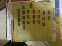
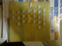
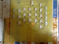
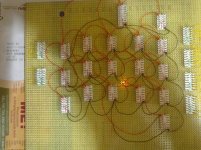
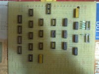
Here are some pictures of my wire-wrap version of my PAL at location 2E Simulation for the S03..
I am doing Ground and Power first.. Then the Outputs to the Inputs..

002.jpg 003.jpg

004.jpg 005.jpg

006.jpg

THANK YOU Marty
 
Last edited:
then I will build the circuit on page 34,

I think the schematic of p.34 is an early design that does not work. The final design seems to be the PAL equations which should work. Not that I am an expert on tape simulators, but the logic equations do what the design descriptions on p.35 says it should do. Maybe the problem is in another part of the board and the PAL is OK?
-Dave

PS an easy example of an error in the p.34 schematic is the very top right gate. It is the NOR gate that forms the RDY signal. It will go high when the three inputs are low. Look at the first input. It is ONL (on line). So if the system is on line, the Ready output can never come on. The proper input should be /ONL.
 
Hi All;
Thank You DaveM for Your observation.. "" Maybe the problem is in another part of the board and the PAL is OK? "" That has come to mind, and hopefully building this will either rule this out or support Your Theory..
That is Why I am building it, so that All Signals can be, sent straight thru, or inverted, Selectable by a switch.. So that any signal can be set to the proper level and I can see the results..
"" The final design seems to be the PAL equations which should work. "" And then comes the Real Work !! Which would mean that I would need to get either the S01 or the S02 working as well.. And hopefully find out where it stops in the Micro-Code, and again hopefully I have the correct Micro-Code listing..

THANK YOU Marty
 
Last edited:
Back
Top