• Please review our updated Terms and Rules here

XT memory expansionc card 384KB... Unknow :(

happymarco79

Member
Joined
Dec 9, 2014
Messages
11
Location
Italy
Hello to all...
This is my first message...:p
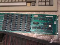
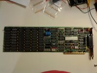
Begin with a classic question, I've buy this used 8-bit memory card for my XT computer (CANON A-200) with 256KB of RAM on motherboard...
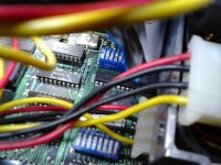
IMAG3605.jpg
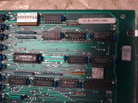
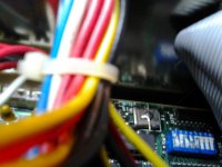
IMAG3606.jpg
I can not find it anywhere the table of two group of dip-switches setting, nor a similar card that that looks like...
Trying 'Random' I managed to get a total memory between PC and card 512KB, but not the 640KB...the card has 6 banks of 8 64KB chips and the last for Parity...
Do you know about this!?
 
Diamond Flower MF-100 Memory Card

Diamond Flower MF-100 Memory Card

i dont know, but would recomend browsing the photo index over at total hardware 99.


Excellent site to find some specs!
Dear Senior member,
I have the above card and according to what I found on this site made sense when I found the graphic; it matches my card to the tee. I followed doc => http://th99.bl4ckb0x.de/i/C-D/52500.htm that made sense to me, i.e. Starting Memory Address 256KB (on off off) and Installed Memory Address 384 KB. I have a Revision B mother board with 256KB installed and working (checked with IBM Diagnostics diskette). Following the IBM "Guide to Operations" pg 5-49 640 Tot Memory (384K + 256K on System Board) I set SW1 and SW2 to what it shows, but below the first line on this page I do not follow those "Card Switches" settings because this card does not have eight switches but six (hope this is a correct assumption). It only made sense to set the dip switches per the guide from the aforementioned link, but I am wayyy NEW to the IBM 5150 PC. I keep getting the 4098 201 memory error.

I would very much appreciate guidance on how to setup this card with my 5150. I guess my PnP days are over. :p

Thanks.
 
I have the above card ...
A Diamond Flower MF-100. It would have been better to create a new thread rather than jump onto the end of a thread concerning a different card.

but I am wayyy NEW to the IBM 5150 PC.
Understood.

Following the IBM "Guide to Operations" pg 5-49 640 Tot Memory (384K + 256K on System Board) I set SW1 and SW2 to what it shows, but below the first line on this page I do not follow those "Card Switches" settings because this card does not have eight switches but six (hope this is a correct assumption). It only made sense to set the dip switches per the guide from the aforementioned link,
Be aware that the MF-100 information shown in the Total Hardware 99 database (TH99) is for the MF-100 only. It does not in any way reference the possible computers to which the card can be fitted. For example, the S1 it refers to is S1 on the MF-100, not SW1 on the 5150 motherboard.

i.e. Starting Memory Address 256KB (on off off) and Installed Memory Address 384 KB.
I keep getting the 4098 201 memory error. I would very much appreciate guidance on how to setup this card with my 5150.
The '40' in '4098 201' indicates a problem at address 256 KB. The '98' in '4098 201' indicates many bits in error, many bits typically seen when there is no RAM at all at the address.

MF-100 settings

MF-100 START ADDRESS: On the MF-100, switches 1/2/3 on switch block S1 set to ON/OFF/OFF. One thing to be careful of: We have seen a lot of people confuse ON with OFF and vice-versa. Refer to the ON/OFF information at [here]. Confusing ON/OFF is one possible explanation for the 4098 201 error.

RAM FITTED ON MF-100: In the MF-100 information within the TH99 database, this is the 'Installed memory address configuration' table. You need the 384 KB setting, however, there is an error in that table. Specifically, the row for '384KB' is wrong. Instead of switches 4/5/6 being ON/ON/ON, it should be ON/ON/OFF

Settings for 5150 motherboard (of type 64K-256K)

1. Switches 4 and 5 on switch block SW1 set to OFF/OFF (all 4 motherboard RAM banks populated)
2. SW2 set for the 640 KB setting (total conventional memory [256 KB on motherboard, plus 384 KB on MF-100])
 
Hello modem7.

I will post to a different thread when it's a different item; thanks for the suggestion.

Can't wait to try the new settings Wednesday night! I would have NEVER known the MF-100 doc within the TH99 DB was wrong. Thank very much for this tip!!! I can say I've learned quite a bit on the 5150. I really do enjoy mine!!! I was lucky and bought a very clean one!!! Granted it had probably a 1/16 worth off dust inside; the box is in excellent shape - very tickled.

I will print out the graphics on switch blocks and keep in handy; I think I had it right, but will verify.

Again thank you very much for your time!
 
Greetings modem7.

Ok here's my results:

On MB SW1 settings: 1 - 7 = off 8 = on
SW2 settings: on off on on off off off off
MF-100 memory board: on off off on on off Note: there's an Every Systems Inc. chip on it.

I have attached a few pics, but they're not the best. I still receive the 4055 201. I believe I have the switches set correctly per the IBM guide for 640KB and your suggestion. My 5150 neophyte brain tells me the MF-100 has problems, but I hope you can share some more information. One thing is when I set the MB to 256KB and run the IBM Diagnostics program it tells me the system has a asynchronous error: => 1101 Asynchronous communications adapter test failed, but when I remove the card all systems checks pass. This sounds like a problem with the card, but I need your expert opinion.

My sincere thanks for your thoughts!
MF-100-Card.jpg
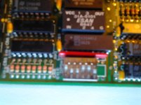
MF-100-Switches.jpg
SW1.jpg
SW2.jpg
 
Hello modem7.

Thanks for the link to minuszerodegrees. A plethora of info that's great. Been studying it for many hours now. The wifey is starting to wonder what happened to me. ;-)

In any event I set the 5150 MB to 640KB, and used the settings you suggested above and the correction you pointed out ( Instead of switches 4/5/6 being ON/ON/ON, it should be ON/ON/OFF). I also read the doc that describes the BLOCK INDICATOR and BIT INDICATOR, and hoping I understood it. I still keep getting the 4098 201, and if I understood this doc a 4098 indicates RAM on an expansion card. So I replaced the chips on bit 7, 4, 3. Again if I understood the doc. Still same results. I made an earlier post, but it's not been posted by the moderator yet (understand it's Christmas). Hence more results of my racking my neophyte 5150 brain. Again I'm seriously thinking the card has issues, but will wait further suggestions/comments/ideas from you/others graciously.

Thanks!
 
Oh I forgot to mention I did the peeks from another doc:
This is supposed to show total RAM (based on MB switches):
def seg = &h40
print peek(&h14) * 256 + peek(&h13)

After the print statement it shows: 640

Then,
def seg = &h40
print peek(&h16) * 256 + peek(&h15)

After the print statement it shows: 576

I was expecting to see 384 the IO_RAM_SIZE on the RAM board.

Thanks
 
I have applied the dip-switch's combinations of the board of which you speak above, but immediately appear "PARITY2 CHECK" ....
So I'm rest in waiting if someone finds some info about my card (or at least from what computer comes)
Thanks to all...
 
Er512pc

Er512pc

I have applied the dip-switch's combinations of the board of which you speak above, but immediately appear "PARITY2 CHECK" ....
That was a 'stab in the dark', because the cards are different.

'PARITY2 CHECK' will be same as the 'PARITY CHECK 2' error that occurs in the IBM 5150 (diagram at [here]). It results from the expansion card sending a signal to the motherboard that a RAM parity error occured.

Trying 'Random' I managed to get a total memory between PC and card 512KB, but not the 640KB...the card has 6 banks of 8 64KB chips and the last for Parity...
When you got 512K total conventional memory, one of two things may have happened:
1. All banks on the card were enabled (384K), but the starting address of the card was 128K instead of 256K; or
2. The starting address of the card was 256K, but only four banks on the card were enabled (256K).

What were the switch settings that you discovered gave you 512K ?
 
I'm sorry for my delay but life goes racing and the world has gone mad...anyway...
Firstly, I did the test with a "IBM Diagnostic XT" software, that recognize the total memory, then excluding the 256 KB on motherboard I can see how many rows are working.
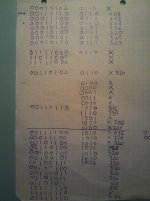
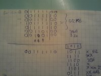
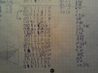
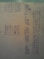
And just because I don't know not even the setting of the Starting Address on card, I had to set 'random' all swithces...the combinations that work discreetly fine are the follow..
[I post these crappy notes because I do first, you will not understand much, but the number of I/0 belong to SW1 and SW2 ... just found a combination from 448 to 512 I tried to move one switch one at a time ...but of course it is impossible to start up 30000 times the PC otherwise I can put it in waste in short time]
The 'X' near 448,512, ecc means error PARITY CHECK in a first time...

IMAG3838.jpg
IMAG3837.jpg
IMAG3836.jpg
IMAG3835.jpg

:lightbulb:
 
Back
Top