Given the recent discussions on Model II keyboards, I have done a little more research on the keyboard differences between the TRS-80 Model II/16 (which we will call the “A” design) and the Model 12/16B/6000 (which we will call the “B” design). The A design was first released in 1978 with the Model II. The B design appeared in 1982 with the Model 12.
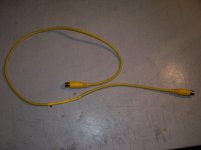
Model II Keyboard and Model 6000 Keyboard Comparison

Picture of Model II keyboard on top and Model 12 keyboard on bottom

The A design keyboards use the 8021 controller which offers a subset of the 8048 controller features found in the B design keyboards. I don't know yet why Tandy moved to the 8048 for the B keyboards but it may have to do with the need for additional ports for the additional function keys. However, the schematics do not show this. (Note: I am not an electrical engineer...I only play one on VCF") ) It may also be that at the time of the redesign, for some reason, the 8048 was cheaper or more available than the 8021. This warrants further investigation. If you know, please educate me.
) It may also be that at the time of the redesign, for some reason, the 8048 was cheaper or more available than the 8021. This warrants further investigation. If you know, please educate me.
Both A and B design keyboards J1 connector and all of the iterations of the Model II video/keyboard boards J2 connector have a 6 pin interface as follows:
1 - Data (from keyboard)
2 - Not Used
3 - Clock (from keyboard)
4 - Busy (from computer)
5 - +5 VDC
6 - Ground
Video/Keyboard interface connector

“A” design keyboards have a 5 pin female connector with the following pin assignments:
1 - Data
2 - Busy
3 - Ground
4 - Clock
5 - +5 VDC
Model II Keyboard Connector

“B” design keyboards have a 5 pin male connector with the following pin assignments:
1 - Data
2 - Clock
3 - Busy
4 - +5 VDC
5 - Ground
Model 12 Keyboard Connector

As shown in the technical manuals, these pin specs are using the standard DIN pin numbering scheme where the pins numbers are NOT ordered physically. They are physically arranged 1-4-2-5-3. This was implemented by the DIN spec so that the pin numbers would not change with a different number of pins in the DIN connector.
Notice that the “B” design keyboard matches the video/keyboard board pins almost exactly using standard DIN pin numbering (with an offset due to the cut pin 2). But, the A keyboards match the pins on a physical numbering basis (1-2-3-4-5). I suspect that the original Model II engineers used a physical pin numbering approach on the keyboard connector but then this was corrected to be DIN standardized when they created the B design.
Now, since the video/keyboard board interface and the keyboard interfaces have not changed between A and B designs, I theorize that an A design keyboard will work on a B design computer with the appropriate rearranging of the keyboard connector. This is an important question to answer since there appear to be many fewer B design keyboards available in the market.
The only way to know for sure is to actually test it with the actual hardware. That will be the subject of my next post.
Model II Keyboard and Model 6000 Keyboard Comparison
Picture of Model II keyboard on top and Model 12 keyboard on bottom
The A design keyboards use the 8021 controller which offers a subset of the 8048 controller features found in the B design keyboards. I don't know yet why Tandy moved to the 8048 for the B keyboards but it may have to do with the need for additional ports for the additional function keys. However, the schematics do not show this. (Note: I am not an electrical engineer...I only play one on VCF
) It may also be that at the time of the redesign, for some reason, the 8048 was cheaper or more available than the 8021. This warrants further investigation. If you know, please educate me.Both A and B design keyboards J1 connector and all of the iterations of the Model II video/keyboard boards J2 connector have a 6 pin interface as follows:
1 - Data (from keyboard)
2 - Not Used
3 - Clock (from keyboard)
4 - Busy (from computer)
5 - +5 VDC
6 - Ground
Video/Keyboard interface connector
“A” design keyboards have a 5 pin female connector with the following pin assignments:
1 - Data
2 - Busy
3 - Ground
4 - Clock
5 - +5 VDC
Model II Keyboard Connector
“B” design keyboards have a 5 pin male connector with the following pin assignments:
1 - Data
2 - Clock
3 - Busy
4 - +5 VDC
5 - Ground
Model 12 Keyboard Connector
As shown in the technical manuals, these pin specs are using the standard DIN pin numbering scheme where the pins numbers are NOT ordered physically. They are physically arranged 1-4-2-5-3. This was implemented by the DIN spec so that the pin numbers would not change with a different number of pins in the DIN connector.
Notice that the “B” design keyboard matches the video/keyboard board pins almost exactly using standard DIN pin numbering (with an offset due to the cut pin 2). But, the A keyboards match the pins on a physical numbering basis (1-2-3-4-5). I suspect that the original Model II engineers used a physical pin numbering approach on the keyboard connector but then this was corrected to be DIN standardized when they created the B design.
Now, since the video/keyboard board interface and the keyboard interfaces have not changed between A and B designs, I theorize that an A design keyboard will work on a B design computer with the appropriate rearranging of the keyboard connector. This is an important question to answer since there appear to be many fewer B design keyboards available in the market.
The only way to know for sure is to actually test it with the actual hardware. That will be the subject of my next post.