• Please review our updated Terms and Rules here

PET 2001-8 Video Display Dead

First as always let me say thank you. I had to go to work today but have got some readings in. Second let me say that I am a computer scientist by training but a consultant by trade. So i am gifted in sounding a lot more knowledgeable than i really am so forgive me for the silly questions. I am serviceable with the Oscope and am learning everyday. I dont have a professional grade scope either. With that said i started at the beginning of the HORZ drive as suggested. Using the settings Dave provided (thanks) and worked out from pin 7 to R33. And that waveform looks correct and the Ohms where 1K ohms through R33. I then moved to R37 just before Q12 and got a flat high waveform nothing like the pictures.

Picture #8 (.5V - 20 us) Output of R33 (CR15) - Input to Q11
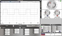
Q11 v2.jpg

Picture #9 (.5v - 20us) Output of R37 - Input to Q12
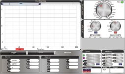
R37.jpg

There seems to be an issue here in comparison with what the schematic shows on #9. I measured Ohms and i get -1 on the meter so i assume that means something is wrong (consultant remember). Not trying to be all smart now but does this sound like a possible issue that we see further down. Should i follow the rest of the chain?
 
A negative ohms reading just means there is still residual voltage there. Powered on, what is DC voltage on collector of Q11 and base of Q12 (both ends of R37) ? Q11 is not functioning.

One more - also what is the DC on emitter of Q12 (or C17) ??
 
Last edited:
Something there is not working.

DC at Collector of Q11 (7.5V); DC at base of Q12 (11.5V). Getting no resistance reading on R37.

DC at emitter of Q12 or C17 (11.8V)

Hope that means something to you.
 
Hmmm - R37 must have some resistance because that's the source for the 7.5V at the collector of Q11.
Be sure the power is off and discharge C17 like with the end of a screwdriver and hold on there maybe 10 seconds to discharge the 12V supply.
Then measure resistance of R37 again. If it is 3.6k then power on and check waveform on collector of Q11. You should be getting a full drive signal of 11.5V p-p.
If R37 checks open you will need to desolder one end and measure it's resistance to confirm.
 
After discharge and off R37 measures 3.6K ohms. The waveform for collector of Q11 is Square Wave 11.5V peak to base. But when measured with a multi-meter i get 7.5V at the Q11 collector (maybe i am not doing it wrong).

After R37 I measure 11.5V at the base of Q12 but there is no waveform. It is just stuck on high at 11.5V (Is that correct?). I also checked the collector of Q12 and I get a Square wave 11.5V peak to base.
 
Your DC meter will average the AC signal so that's why only 7.5V DC. So Q11 is ok. Base of Q12 will only be a .6v p-p signal so that is why you might not be seeing it. With 11.5v p-p on collector of Q12, it is ok too.
We are getting back to where we were last night. What is the waveform on collector of Q13 ? It should also be 11.5v p-p. Also what is the DC on that point? It should also be midrange like 6 to 8 volts.
 
Something there is not working.

DC at Collector of Q11 (7.5V); DC at base of Q12 (11.5V). Getting no resistance reading on R37.

DC at emitter of Q12 or C17 (11.8V)

Hope that means something to you.

You'll have to lift one leg of R37 to take it out of circuit to measure the resistance.
 
Collector Q13 Square wave 0 to 11V. Voltage on Q13 collector moves around a little but around 8.5V the first time but then measured again and it is 11.7V and stays there after repeated measurements. (Sorry for delay, other chores)
 
So i moved on to Q14 and I am getting .3V on the outside post of Q14 and getting 12V on the center post. With that said Q14 has only 2 post attached to the board not the center post.
 
put your scope on base of Q14. You should have a healthy square wave maybe .6 to .8v p-p

center post of Q14 is the collector so probably just the heatsink metal.

post a picture of the Q14 base waveform
 
Last edited:
I need to get to bed soon so I'll keep talking. Google for the TIP55A datasheet which gives you the shape and leads of Q14. Notice the shape of the waveform #12 in the schematic.
See how the duty cycle of the base is two graticules on and one graticule off? That is 66% duty cycle. That is important because the on time of the output transistor loads the coil of the flyback transformer so when Q14 turns off the energy is released
to produce the high voltage, etc. I'm guessing the waveform on the collector of Q14 is supposed to be like 100V p-p which it must not be. The problem must be in the drive signal to Q14 or Q14 itself is bad.
 
THank you. Sleep is a good idea. I will do as you said and look at ordering a Q14 maybe run it in Parallel. As always thank you and i will let you know. Goodnight!
 
Ok saw your base waveform. That is not good at all. Make sure the emitter of Q14 is grounded. Make sure waveform 11 on Q13 has a good 50% on time duty cycle which I think it is.
I'm thinking Q14 is bad. That curvature of the base waveform happens with a bad base/emitter junction. Put your scope on collector of Q14. There should be a spike present.
If not, Q14 definitely bad. Does it get warm? Of course power off before touching. You would get an awful shock from that pulse. If transistor is stone cold then it is bad. A base waveform
like that would heat a good transistor tremendously.

PS - and goodnight ...
 
Other that buying on ebay from outside the US where there are some TIP55a listed is there any modern alternatives to the TIP55A?
 
According to NTE's website, they show a cross reference for TIP55A with NTE2310:

http://nte01.nteinc.com/nte%5CNTExRefSemiProd.nsf/$all/86B36CCF24DC424A852579100082BCED?OpenDocument
 
The NTE2310 is probably the way to go.
Since you're ordering parts, I would recommend replacing C17 47mfd 16V just to be sure. If that capacitor is weak, it lowers the power provided to drive the output transistor which causes it run hotter.
If something caused the failure, that is a likely candidate.
 
thank you all. Found some parts. I have not done the heat test but will when i get home this evening.
 
Back
Top