• Please review our updated Terms and Rules here

Analog Computer "Down Under" EAI TR-20

inotarobot

Veteran Member
Joined
Feb 7, 2014
Messages
1,090
Location
Melbourne, Australia
Hi all,

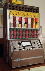
As some of you will know in November, I bid on eBay and won a EAI TR-20 Analog computer.

After a long interstate drive (12 hrs each way) in early December, to pick it up, its finally home.
I transported it on the back seat of my family sedan; a SAAB 9.5. It was wrapped in blankets to protect it, and sat on a padded sleeping bag as an extra protection against road bumps. Mind you the interstate highway I traveled on, often at 110km/hr was very smooth.

The only jarring it may have got, was when I drove the 80m up the 20deg angle gravel driveway, correction creek bed, at home. Just need $20,000 , as quoted by earthing moving civil contracting companies to fix my driveway.

On actually seeing the TR-20 for the first time in Adelaide, I was quite thrilled. It is in mint condition. The seller, a charming gentleman, took the time to show me it running and also explained a lot about it. During that brief power up all, he pointed out all the overload lights toggling then going out. We did not do any other functional tests.

It was around 9pm and in hindsight, I should have just gone to a motel after the long drive, and then gone the following morning to pick it up; as I would have had more time and focus to take in the information I was being shown. Also I think I would have had more power on time to get familiar with the unit. That way I would have had a better reference point, to know if any future power on issues or possible damage could have been caused by my chosen method of shipping.

Finally a few days ago, I actually got some time to focus on the TR-20.

1. Put power to it and ended up will more than 50% of the overload lights on.

2. Powered it of. Removed and then re-seated front panel, after checking the contacts, found all are like new, and none bent.

3. Next power up and most of the overload lights went out. Just had three hard on, and one flickering. +10v and -10v rails are ok on Fluke multimeter.

4. Did the amp balance check, 14 passed Ok

5. Checked amp outputs with feedback block in. 11 were at zero volts, 9 were reading +15v

6. Ran each of these 11 Ok amps from step 5, in Inverter mode, first with +10 then with -10v. 8 passed. 3 failed.

So in summary it seems I have only 8 good amplifier's to start.

Faulty one are 1,2,4,11,12,13,14,15,17,18,19,20

Planning over Christmas to have some time to test amps.

Bought some 22 pin single row connectors to make both an extender and also a separate bench test unit.

Looking forward to doing my first calculations on it.

The unit also came with a full set of patch leads, manuals and some spares, but no spare Coppers.

Now I want to buy or find or be GIVEN (LOL) a matching HP plotter.
 
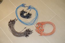
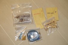
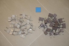
Pics of the accessories that came with my TR-20

Pics of the accessories that came with my TR-20

As you can see my TR-20 came with quite a few important accessories.

These are the patch cords, and interconnect plugs, that are used to create the program this analog computer will execute.

DSC00418.jpg

DSC00420.jpg

DSC00426.jpg

Also there are spare front panel connecting, spring loaded contacts
 
Last edited:
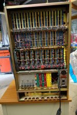
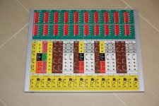
my TR-20 analog computer removable front "programming panel"

my TR-20 analog computer removable front "programming panel"

On this model analog computer the front patch panel that one creates the 'program' for the computer to execute, is removable.

This was done to allow to allow the use of multiple front panels, to be separately patched and left as a 'program' to be run again.

DSC00429.jpg
 
I have a TR-10 and when I got it none of the OP-Amps work. On most of them the problem was chopper relays were gummed up. I am pretty sure the TR-20 uses the same chopper relays. I built a test box with a valve socket so I could check they were working out of the computer, but basically all it does is take the 6.3v ac from TR-10 and feeds it to the coil on the relays.
 
Hi again all.

OK need help please on this EAI TR-20

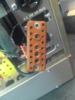
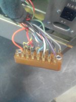
The unit has a display out connector, on the back right hand side, directly below the AC main 115v or 240V ac power in connector.

Personally, from 40+ years working in industrial electronic, I very much dislike the location of this connector, as none of its cabling appears screened (mind you I was tired when I inspected this area, and may have missed the screens), especially since it has only voltages in range -10 to +10v dc, based on its location to the input power cable, makes me wonder just how much interference or modulation the mains power puts on this output signals.

I CANNOT identify it correctly. Wish to buy or maybe "be given" a mate for it. Prefer not to change it for a later style, as I would like to keep this part of the hardware as original as possible.

IMG_20130902_021449.jpg

IMG_20130902_021537.jpg

Its Amphenol. There is no part number on the connector.

In the EAI Maintenance Manual this Amphenol connector is defined as J57, on the EAI Drw D045 078 0W called Wiring TR-20 Computer.
And this connector routes the signals from the Display Module located in my machine in slot 17 of the Non-Linear Elements plug in row, out to remote devices like a plotter or the EAI Repetitive Display unit.

I have looked in my old Newark catalog No 105 dated I guess 1970's or earlier, and NO sign of this family.

Can anyone of you foke ID the connector and maybe even point me to a source for 1 ?
 
I have a TR-10 and when I got it none of the OP-Amps work. On most of them the problem was chopper relays were gummed up. I am pretty sure the TR-20 uses the same chopper relays. I built a test box with a valve socket so I could check they were working out of the computer, but basically all it does is take the 6.3v ac from TR-10 and feeds it to the coil on the relays.

Hi Dave,

Thanks for the reply, and the advice.

I was thinking of adding a connector to a jumper programmable test box, I made 20 years back, so I could test the amps.

Makes sense to test the Choppers separately.

My choppers are part numbered as follows on outside of can

EAI 530 042 0
Instrument
Chopper
James C-2335-A


Googling this shows James Electronics Inc, were they the actual manufacturer of these choppers.

So far not found any data or service info on their products.

Amazing piece mechanical engineering inside the metal can.

They are extremely fine mechanism, that has 4 fine thread screws for adjustment of the contact gap.

Would be keen to find some documents that describe servicing these choppers.

I will take some pic of the inside when I have daylight to get good pic, and post here.
 
Hi all,

well the weather was so hot here in Melbourne, Australia today and this evening that I could not sleep.

So what did I do ? you guessed it I googled for information on the electro mechanical choppers used in DC Chopper stabilized amps, used in my EAI analog computer.

Maybe not the "mother lode", or GOLD nugget but I came across the following link

http://www.landandmaritime.dla.mil/Downloads/MilSpec/Docs/MIL-DTL-83729/dtl83729.pdf

and on reviewing it, I found a wealth of info on testing the choppers.

Fig 1. Circuit for measurement of the dynamic contact resistance,
Fig 2. Circuit for measurement of the waveform characteristics,
Fig 4 Alternate method for Dwell and Dissymmetry measurement,
to name a few.

So off to sleep now and print 83792 doc out fully in the morning. May read it at breakfast.

Mind you I as yet have not found any literature from James Electronics Inc. , the maker of many Electro-mechanical Choppers.

There must be data and maintenance docs somewhere. These products entered Military equipment and I see MSN for some of the product range.

Guess time will tell what turns up.
 
Last edited:
I also found this navy manual.

http://web.ornl.gov/info/reports/1968/3445605496479.pdf

These op-amps are similar to the TR-20 ones. This is the jig I made for testing the chopper relays which are the same in the TR-10 and TR-20

Chopper-Tester.jpg

Sadly my TR-10 does not have a display connector, and I must admit I have never seen one like that. It looks to be a special.

I have some HP A4 plotters, which need some work on them, but I guess shipping from the UK would be prohibitive.....

There are many tutorials and application notes here:-

http://bitsavers.org/pdf/eai/applicationsLibrary/
 
INSTRUMENT CHOPPER Insides photos - EAI / James

INSTRUMENT CHOPPER Insides photos - EAI / James

Hi again,

as promised here are some photos of the inside of one of my James Instrument Chopper's model C-2335-A, from my EAI TR-20

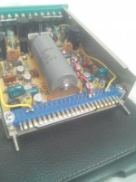
First photo shows the metal can 9 pin plug in chopper relay, mounted on the EAI Dual DC Amplifier 6.712

IMG_20130902_033537.jpg

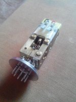
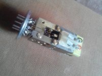
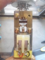
These next 3 photos show the complex mechanical mechanism when its removed from the "can"

IMG_20130903_082602.jpg

IMG_20130903_082448.jpg

IMG_20130903_082947.jpg

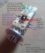
This one has 2 independent sets of change over gold contacts.

following is an annotated photo of this exquisite mechanical chopping relay.

Instrument Chopper insides described.jpg

Looking at it carefully, I think the "Domed head" of the contact adjusting screw, looks like its either a pearl or some type of ivory.
Their finish appears too pearlescent looking, to be a man made material.

Back in the 1930 to 1960's many specialists equipment makers, still used natural materials, unlike today where most materials are synthetic.
 
Looking at it carefully, I think the "Domed head" of the contact adjusting screw, looks like its either a pearl or some type of ivory.
Their finish appears too pearlescent looking, to be a man made material.
Back in the 1930 to 1960's many specialists equipment makers, still used natural materials, unlike today where most materials are synthetic.
Ivory!
Who would have thought that the purchase of a vintage computer might be illegal.
 
Congratulations Inotarobot, I saw your machine on eBay and pondered bidding on it. But, sadly I have too many projects which aren't getting done as fast as I'd like. I'm glad it's in good hands, and even more glad that you're a member here and will no doubt be keeping us enthralled on your steps and stumblings in bringing it back to life, documented for us all to gawk at :)

Regarding that connector. If you can't find a mate for it, and you only need one then why not build it? Using the plug itself as a template it should not be too difficult -
Find pins that seat comfortably in the sockets, solder some flying leads with the same insulation colours to them. Using a rectangular piece of scrap plastic, drill holes in it to match the pin spacing. Superglue your pins to the plate. Bind with dental floss, polyester thread (or my favourite, Kevlar thread) and finally drizzle epoxy over the back. For this last step you could make a cardboard moulding shield temporarily sealed with plasticene to keep the epoxy in.
As an example here's a 20mA current loop connector I made from two old PC floppy drive plugs: http://www.vintage-computer.com/vcf...oop-Connectors&p=363590&highlight=#post363590

Steve
 
Back
Top