• Please review our updated Terms and Rules here

Getting closer to Model II improvements...

JonB

Veteran Member
Joined
Jan 26, 2014
Messages
1,652
Location
South Herefordshire, UK
Hi all

Here's what I have planned for my lovely MII.

  • Install a separate 12v power supply for the monitor to fix the wobbles. Needs a 22 ohm wire wound resistor to load the existing power supply.
  • Replace noisy mains-powered fan with a quiet 12v model.
  • Replace SS 8" drive with a DS drive (which needs fixing).
  • Fit Hans01 LoTeck IDE adapter bridge card, and LoTech adapter.
  • (Long term) Derive a device driver for the LoTech SSD hard drive.
  • Fix the manual reset circuit.

So, some components turned up today: for the reset circuit, a quad NAND gate IC (CPU board U30) and a multivibrator IC (CPU board U27). I'm guessing one of these is at fault. There is also a gate at U29 that may be causing it. We'll see.

And an ENORMOUS resistor:
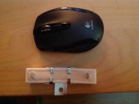
image.jpg

Yes, it really is bigger than a typical full sized mouse, but that's because I over specified the wattage - it's 50W - because that's what the supplier had available. Still very cheap though, so where is the harm?

I know that other MII owners have done these some mods before - do any of you have specific advice before I begin?
 
Last edited:
@JonB

If you take of the front bezel, you can 'easy' remove the 220 volt blower and reach some empty space
beside the crt to place the 12 volt powersupply.
There is no need to remove the bolts, you can reuse them, just block them with your fingertips.
The 22 ohm resistor is oke, you can use it. Give it some space as it can get rather hot.

Re: front bezel, that is good to know, but I think I may need to disassemble it further to get at the 220v connector block. Not looking forward to this!

Re: resistor, it's the ohmage you recommended on your "revival" thread. I plan to mount it on a piece of the steel chassis for heat dissipation. The obvious place is on the PCB rack adjacent to the tube neck, but the CPU card is on the other side. So maybe on one of the tube chassis mount flanges, but there is no ventilation hole above it. Where did you put yours?

By the way, your guidance on these threads has been invaluable!

http://www.vintage-computer.com/vcforum/showthread.php?43673-Revival-of-a-TRS-80-Model-II
and
http://www.vintage-computer.com/vcf...-Questions-about-a-new-switching-power-supply

Cheers
JonB
 
@JonB

HPIM0153.jpg
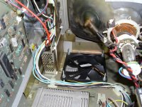
I put the powersupply just beside the left stud of the monitor. I used some double sided tape and a few tie wraps to fix it.
There you can see how to reach the cooler. First turn on two nuts to get hold on the bould.
If you take away some flatcables on the backside you can disconnect the 220 volt power with a long screwdriver.
To make the job a lot easier, you have to take out the cardcage too. Be very carefull with the neck of the picture tube, the glass is very thin !!!!!

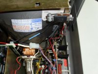
HPIM0157.jpg
On this picture you can see where I put the resistor, on the right side just above the monitor.

What a real awfull job is to repair the monitor bord which is connected to the powersupply. It took every day more time before I
got a stable picture on the monitor.
There was a problem with horizotal line oscilator, I could locate it with cold spray. It took me a whole day to do the job, that was awfull.
 
I'm curious. Wouldn't it be better to just replace the original power supply with a modern unit that supplies everything you need, like a RQ-125D, rather than generate all that waste heat with the resistor? Or am i missing something. You are planning on using a modern 12v power supply so the originality argument is moot.
 
..but the cost argument isn't!

RQ-125D is £57 here.

12v power supply and resistor about £6, which means I can chuck it away if I decide to go down the Meanwell route (yes, I know it's the "right" way to do this, but the cost.. it's more than the Model II cost me). Maybe if I get the Hans-01 going with a CP/M variant I will do it, but as you can see there are other things pending.
 
Yeah, understood, that is a significant price differential. RQ-125D is $34.95 on Jameco in the US.
 
@Pete, JonB

Using a 12 Volt power supply
Pro: Low costs, rather easy to replace

Using a new multi voltage powersupply
Against: Higher costs, much more work to do
 
Fix the manual reset circuit - DONE. :D

It was the 74LS132 at U30 as I suspected. Would hate to have to debug this thing otherwise, there is no access to the boards when running, and no obvious way to use a card extender. I suppose you'd have to run it caseless somehow. Tricky, but not necessary, thank heavens!
 
You can use my hans-03 + hans-04 as a card extender. :D

Are there no limits to your creativity, Hans? Nice!

Anyway... Why do you think the fan is outside the card cage? It seems to be providing airflow to cool the tube. I wonder if it's really necessary. It doesn't even flow directly onto the power supply (the video board is in the way). So what's the point of it?
 
Tandy must have thought better save than sorry. :)
How bigger the case how bigger and stronger the fan.
By the shape of the case there is an airstream upwards out of the computercase, the rising hot air from all the components, like cards, supply, diskdrive and
video are taken with this stream out of the case.
I think you don't need a fan at all, but I take no risk and the 12 volt fan is very silent, so don't worry.
 
OK.. time for an update.

Eventually the little power supply turned up from China. £3.50, amazing. I have a 12v Antec fan already (out of an old PC) which is the right size and very quiet, and as you know I also have the humongous resistor. Time to wire the thing up!

We need to make up some cables first.

  • 240v power supply cable. This will connect to the Model II's mains connector block using the 240v fan's connections, which are screw terminals. The other end needs to be stripped to fit into the 12v power supply's screw terminals. I used normal 2 core mains power supply cable such as you would find attached to the back of any old appliance that doesn't have an earth.
  • 12v monitor power supply cable. This is stripped at one end (for the 12v supply terminals) and the other end is fitted with female Amphenol pins from a PC hard drive power supply connector.
  • 12v connector to dummy load resistor. These have spade connectors at the resistor end and male Ampenol pins, again fom a PC power supply connector at the other end.

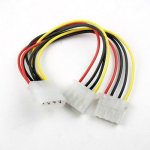
To get the Amphenol pins (male and female) you are going to need a hard drive power supply splitter like this:

12v Ampenol splitter.jpg

To remove the pins (male and female) from the plug housings, you need to bend the little tabs inwards. Look carefully at what is preventing them from coming out and you will see what I mean.

Retain an inch of cable on the end of each pin, strip it back and splice to some suitable wire for the 12v connections. Use heat shrink tube to insulate the soldered ends and part of each pin so that when inserted in the Model II connector, no bare metal is showing.

Let's press on...

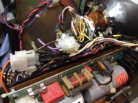
The 12v connections look like this. You split the Amphenol connector and connect the resistor to the power supply side and the 12v power supply output to the monitor side. Be wary of the monitor supply polarity. On my Model II the 12v line is purple and 0v black going to the monitor. The Model II power supply end is orange and black, but since these are connected just to the resistor, polarity does not matter.

12v connectors close up.jpg
 
The mains connector is tricky, because the connector block is right at the bottom of the chassis, under all the nasty high tension wires for the CRT. I definitely do not want to be poking my hands down there. The solution is a lot of fiddling and a magnetically tipped screwdriver. Remove the Model II 240v fan connector terminals by unscrewing the two middle connectors. Take the fan out and put it to one side - you can do this by removing the front bezel, but even with this out of the way, space is limited. It's going to take a while, fiddling with those fan screws, so be patient. Now's a good time to install the 12v fan, by the way.

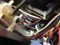
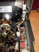
Attach the 12v power supply cable to the Model II distribution block at the connectors formerly in use by the fan. Lots of fiddling. Take care not to touch any of the high tension wires, just to be on the safe side. This is what it should look like.

Mains wiring.jpg

The blue / yellow connectors are for the 12v power supply.

Now you need to route all the cables that go to the 12v power supply and connect them up.

Here's the wiring:

12v PS Wiring.jpg

From top to bottom:
  • +12v to fan (red) and monitor +ve supply (Yellow/Red).
  • -12v to fan (black) and monitor -ve supply (white/red).
  • GND, not connected because the case is grounded to the CRT leg. Maybe I should connect it to the -12v?
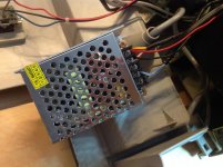
  • 240v mains Neutral (blue)
  • 240v mains live (brown)

Incidentally, that little brown screw due north of the +12v connector is the voltage adjustment trimmer. Just to be safe, I checked the thing really was giving 12v before connecting it up (it was 12.35v, so I trimmed it back to 12.15v).

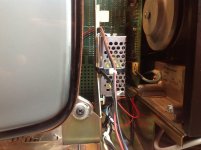
I decided to mount the supply on the CRT's chassis leg on the floppy drive side.

12v Pwer Supply in situ.jpg

It's attached with a zip tie.
 
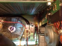
The fan looks good..

Fan and Pwr supply in situ.jpg

..no LEDs!

Finally we need to attach the resistor to something and I chose the other CRT leg. This should provide some heatsink capability as the resistor may get hot.

You can see it to the right of the CRT:

Resistor wiring.jpg

As for the rest, it is a simple matter of "reassembly is the reverse of disassembly".
 
In use..

In use..

So, is this a worthwhile upgrade?

Well, I think it's a big yes from me, thanks to the stable picture and reduced noise. I still have some image wobble but it is very slight and unconnected to the floppy drive operation. I may wire the 12v fan into the Model II supply and / or stick a great big smoothing capacitor in there.

Total cost was £10 plus an afternoon (the only parts I needed were the power supply and dummy load resistor; everything else I had lying around.

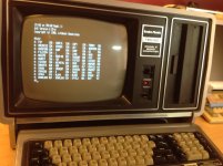
Nearly rock solid.jpg

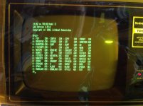
Oh by the way, I'm experimenting with amber filters because I find the colour easier on the eye:

Amber experiment.jpg
 
Back to the to-do list!

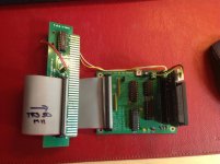
Here's the Hans-01 to LoTech bridge card. I put it together while waiting for the 12v supply to arrive from China.

LoTech Bridge card.jpg

Nothing much to report here. Assembly was very straightforward. The LoTech adapter itself and the CF card adapter are straight off my Model IV with the one chip swapped out. It won't fit in the card bay as-is, but it is only temporary. Once I prove it works I can modify it for a more permanent fit.
 
Today, the Chinese power supply blew up. I haven't even used it that much! So I am back to standard power. Grr grr grr etc!

12v 2A should have been enough surely? For the screen and 12v fan?
 
Back
Top