• Please review our updated Terms and Rules here

NEW, to me, DEC PDP8E --- Part 2

Mike_Z

Veteran Member
Joined
Dec 1, 2013
Messages
1,713
Location
Near Milwaukee Wisconsin
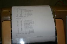
Well, it's been a few months since I've even looked at the PDP8E. Last December I was fighting two stuck bits in the major registers. I fixed one. There was a bad D flip flop in the MB register. But the other was driving me nuts. I kept chasing in circles looking for the problem. Well, I decided that I needed a break. In fact I drove down to see Jack Rubin. He and some friends were going on a rescue mission, so I went along. They picked up a bunch of older computer 'stuff'. I got a Teletype ASR 33 TZ. Spent the last two months cleaning, oiling, fixing, etc, and I got the thing to work. I wanted it to connect up to the PDP8, but since it wasn't working, I connected the TTY to one of my homemade CP/M machines with good results. I still have a few bugs to iron out, like the control key doesn't work right, but I think that is a minor fix, when I get some time.
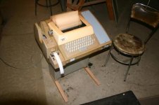
IMG_0209S.jpg
IMG_0213S.jpg

Anyway, I have gotten back to the PDP8E and have gotten the problem repaired. There was a problem with one of the input MUX bits, on the input side of the adders. So, I've loaded the incrementing accumulator program,

7001
2101
5001
5000

And it has worked many times over the past three days. So, my next project is to repair and install a 8650 UART board. But.... before I go there, I'd like to test the PDP8E a little more to be sure it is fully functional. I'm looking for a couple more short test programs that I can key in from the front panel to run for a few days to check out all the functions of the machine. And to help me become a little more familiar with the use of the front panel. Can anyone point me in the right direction? Thanks Mike
 
Hi All;

Congratulations, Mike, on both getting the Stuck Bits fixed, and on obtaining the Teletype..
I don't know exactly How small or How short of a program that You might be thinking of,
But, as I am sure that You know Daver2 wrote many small and short pieces of code for me when we were attempting to get my PDP 8i clone going.. So, I am not sure if this is what You are looking for or if it will work on Your machine..
But there are plenty of small programs that cover many small areas that You could use to check out different parts of Your machine.. Working up to being able to run DEC PDP 8 diagnostic programs..

THANK YOU Marty
 
Thanks for the programs. I started this morning with the Group 1 program and it has worked just fine a few times. My old brain has to get used to what I'm looking at on the front panel and the selector switch. I have trouble with the auto increment of the address and get confused with what address the data is actually in.

For example, If I do a Address Load of a particular address, say 0200, the address lines will indicate 0200, but if the selector switch is on MD, I do not or may not see the actual data at 0200. I have to do an Examine to see the 0200 data, but then the address lines show 0201. Did I say that correctly?

One other minor point, the address lights are always addresses regardless of what position the selector switch is in, and one more than actual?

Then lastly, when is the instruction executed? If the addresses line shows 0201 (meaning I'm actually at 0200) and the data says 7001 (IAC), that instruction is waiting to be executed? So if I single step, the accumulator should be incremented after I continue once.

Thanks Mike
 
Provided that you're not Single Stepping, when the 8/e halts it does so at the end of a machine cycle (at the end of TP4 which is actually just entering the next machine cycle) at the end of the current instruction and is ready to do a Fetch cycle so the PC has already been incremented or loaded with the new value. This means that the PC is pointing to the next address to be accessed and all other data refers to the instruction just executed. In Single Step it stops at the end of each cycle so the address and data on the front panel depend on which cycle was just executed.

Some of the front panel switches cause the 8/e to execute a single cycle in a similar way, so Examine and Deposit also stop after 1 memory access with the PC ready for the next Fetch. The (Extended) Load Address is slightly different of course and doesn't cause a PC increment otherwise you really would have something to get your head around! Because of this Loading an Address doesn't cause the data for that address to appear on the front panel because it didn't cause a memory cycle.
 
Last edited:
Well... talk about being confused! I moved on to the Group 2 instructions. This list is a little longer than Group 1 and caused me to make a mistake in the middle of the listing. So in order to repair it, I did a Address Load, which causes the correct address to display but the previous address's data. So, I'm questioning if I'm at the correct spot. If I do an Examine, the address increments and the data I want to change is displayed, but now I'm too far along to change it. So is this correct?

Address load 0210 --- Address display will show 0210, but with data from 0207 or the data from last addressed cell

If I do an Examine --- the Address display will show 0211 with the data from 0210

If I now do a Deposit --- the Address display will show 0212 and the Switch Register will be deposited into 0211

SO....... if I want to correct 0210 data I have to;

Address load 0210 --- Address display will show 0210, but with data from 0207 or the data from last addressed cell

If I do an Examine to be sure of the wrong data --- the Address display will show 0211 with the data from 0210

Then I have to do Address Load 0210 again

If I now do a Deposit --- the Address display will show 0211 and the Switch Register will be deposited into 0210.

I have also noticed the mentioned difference between the Halt and Single Step switches. I have always considered Single Stepping as running an entire instruction, but here that is accomplished with the Halt switch down. The Single Step switch down does a single cycle. That is something I want to understand better, but later. What happens if both the Halt and Single Step switches are down?

The good news is that Group 2, the Skips all work. I have run them a number of times and only had self induced errors. Another curious, but mostly likely correct front panel event is that when a skip instruction has been executed, the address display is not the next address, but the next after the next, which makes sense, but again was not expected.

My old brain has quite a few preconceived ideas of how things should work and it must be obvious that I was not a DEC engineer. But.... I like things that are different to my way of thinking, because it makes me look at things from a different perspective.

Mike
 
What happens if both the Halt and Single Step switches are down?

Single Step works the same whether or not Halt is also down.
 
Actually, I want to finish testing the machine using the programs you gave me. Then repair one of the 8650 boards I have, connect up the TTY Model 33 to it and test that.

What is MAINDEC's? I have heard about OS/8 and had thought that would be the software to run. What do you think are there other choices? Thanks Mike
 
MAINDEC are maintenance programs to checkout all corners of the system before running some real system on it.
Usually the MAINDECs are papertapes that you load from the teletype.
 
We're struggling with a similar chicken-and-egg situation here in Australia - not sure if our binaries are bad or if our load procedure isn't working. I've toggled in the RIM loader, loaded BINLDR.RIM with TerraTerm set at 8N1, binary transfer. I've verified that BINLDR loaded correctly, but I can't seem to load .PT or .BN files. What terminal emulators/serial protocols are people using? I've always used GTTY for file transfer but that won't run under Win7-64, which is what I have on my laptop (no need for whining about using Win7).

I was also able to successfully load another .RIM file, MAINDEC D1EA.RIM, but no luck with binaries. Any ideas?

Thanks,
Jack
 
Hi All;

Jack, I used TeraTerm for all of my Windows Transfers, and I have had No trouble with it.. I used it when working with both my PDP 11's and PDP 8i clone..
Be sure to Check the Binary Box when Sending any file or it sends (I think) Ascii..

THANK YOU Marty
 
I've been testing my M8650 Uart boards. So far I know that the clock works correctly and the Device Select and MD9-11 decoders work right. To move on I want to make timing program. I know that I can make a delay of about 15.6 ms with TAD 2101 and JMP 5000. The TAD is 2.6 us and the jmp is 1.2 us. So that sum, 3.8 times 4096 is about 15.6 ms. I'd like a delay of 100 ms or so. If I could loop through this 7 times I'd have it. I figure if I could get 7770 into an address and then increment and skip on zero that would work, but I'm not seeing it. Thanks Mike
 
I found a program that works . Found it in my Intro to Programming book. But while I was learning how it works I noticed that when my M8650 board is in the computer and the selector switch is set to STATUS, the #2 lamp INT BUS is blinking fast. Does this mean that the 8650 is interrupting the machine? This does not happen with the 8650 out of the bus. Mike
 
Well.... I've had partial success. On the Uart board with the blinking Interrupt request line, the receive flag flip flop was not behaving properly. With that changed I have gotten that 8650 to receive a character from the teletype. But I can still can not print. I have a hunch that the problem maybe the delay line DL1 in the clock circuit. I don't know much about it, but I have a good TTL signal into it and hardly anything out of it. Also the device is kinda loose on the circuit board and by just touching it, the little bit of output goes away. Does anyone know what is in this thing? The schematic says it is a 30 nano second delay line. Where would anyone get one of these? Could I just insert a couple 7404 inverters to get about 30ns? Thanks Mike
 
Hi All;

Mike, "" Where would anyone get one of these? ""
There should be a number or a part number on it somewhere, just put it into Your favorite Search Engine, and see what comes up..
Sometimes it can be very surprising..
"" Could I just insert a couple 7404 inverters to get about 30ns? ""
Yes, But You might have to search thru more than a few to get the 30ns You need, unless it isn't critical..
Also You could try a 7414 instead, and it should put in a cleaner signal on the output..
But, again it might take some searching to find something with 30ns..
"" Does anyone know what is in this thing? ""
It's basically alot of wire and maybe some small Caps, so the signal has to travel a looong ways before coming out the other end, hence the Delay..
The Delay lines were made so that it was close tolerances to what was needed, where as the Ic's delay time could vary alot between each Ic, and so could not be used, in most instances..

THANK YOU Marty
 
Thanks for the reply. Do you know what the purpose is of this thing. My documentation doesn't even mention it. I did google it and there are a few places that say they have it and I should ask for a quote. I tried Mouser, where I get most of my parts and they have some surface mount devices. I suppose I'll try the 7404 or 7414 chips to see that helps before I spend any money. Thanks Mike
 
Hi All;

Mike, "" Do you know what the purpose is of this thing. ""
No, since I don't have nor used anything having to do with a real PDP 8..
You will need to talk to SomeOne has actually has one..

THANK YOU Marty
 
Back
Top