• Please review our updated Terms and Rules here

Need some help with an Amstrad PC1640

Monkeyclock1234

New Member
Joined
Jul 10, 2016
Messages
9
Location
Aberdeen
OK So when I boot it up it goes through the checks and then goes to Memory Error: Parity Error. I have tried cleaning the board but to be honest I have no idea where to start looking as this is my first foray into vintage computing. Can anyone help?
 
Simplify the machine as much as possible to start with - remove any extra cards like sound, Zip, whatever, so you have just the basis. Then remove as much RAM as you can to leave the board in the minimum state possible, then go from there. Of course it would be useful is the Amstrad ROM gave us a little more info, like the address of the issue.
 
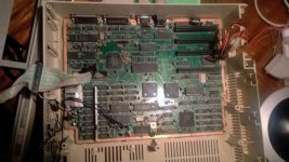
Check the chip numbers to be sure but I think the RAM is the 18 chips located on the lower left of the image.

If not socketed, well, in theory, one can directly unsolder the chips. Lots of work and easy to make mistakes.

Check the traces running between all the RAM chips and the CPU. Maybe you will get lucky and one trace got damaged causing the parity error. A short piece of wire can be used to jump over breaks in a trace.
 
so I have checked the traces and other than some black marks on some bits it all seems okay...The batterys had leaked previously by the looks of things as there were a few signs of corrosion which i cleaned off. Still getting the same error however :(
 
Stupid Question...Where is the ram? and how do I remove it? All the chips are soldered onto the board. View attachment 32007

Hi there,

POINT 1.. THERE ARE NO I repeat NO stupid questions on this forum.!!!!!!!!!!!!!!!! You are amongst like minded friends here. We cannot know everything about everything, and this forum is about helping, asking and providing information and guidance.


Background

What is a processor or memory parity error?
Parity checking is the storage of an extra binary digit (bit) in order to represent the parity (odd or even) of a small amount of computer data (typically one byte) while that data is stored in memory. The parity value calculated from the stored data is then compared to the final parity value. If these two values differ, this indicates a data error, and at least one bit must have been changed due to data corruption.
Within a computer system, electrical or magnetic interference from internal or external causes can cause a single bit of memory to spontaneously flip to the opposite state. This event makes the original data bits invalid and is known as a parity error.
Such memory errors, if undetected, may have undetectable and inconsequential results or may cause permanent corruption of stored data or a machine crash.
There are many causes of memory parity errors, which are classified as either soft parity errors or hard parity errors.
Soft Errors

Most parity errors are caused by electrostatic or magnetic-related environmental conditions.
The majority of single-event errors in memory chips are caused by background radiation (such as neutrons from cosmic rays), electromagnetic interference (EMI), or electrostatic discharge (ESD). These events may randomly change the electrical state of one or more memory cells or may interfere with the circuitry used to read and write memory cells.
Known as soft parity errors, these events are typically transient or random and usually occur once. Soft errors can be minor or severe:
Minor soft errors that can be corrected without component reset are single event upsets (SEUs).
Severe soft errors that require a component or system reset are single event latchups (SELs).
Soft errors are not caused by hardware malfunction; they are transient and infrequent, are mostly likely a SEU, and are caused by an environmental disruption of the memory data.
If you encounter soft parity errors, analyze recent environmental changes that have occurred at the location of the affected system. Common sources of ESD and EMI that may cause soft parity errors include:
Power cables and supplies
Power distribution units
Universal power supplies
Lighting systems
Power generators
Nuclear facilities (radiation)
Solar flares (radiation)
Hard Errors

Other parity errors are caused by a physical malfunction of the memory hardware or by the circuitry used to read and write memory cells.
Hardware manufacturers take extensive measures to prevent and test for hardware defects. However, defects are still possible; for example, if any of the memory cells used to store data bits are malformed, they may be unable to hold a charge or may be more vulnerable to environmental conditions.
Similarly, while the memory itself may be operating normally, any physical or electrical damage to the circuitry used to read and write memory cells may also cause data bits to be changed during transfer, which results in a parity error.
Known as hard parity errors, these events are typically very frequent and repeated and occur whenever the affected memory or circuitry is used. The exact frequency depends on the extent of the malfunction and how frequently the damaged equipment is used.
Remember that hard parity errors are the result of a hardware malfunction and reoccur whenever the affected component is used.
If you encounter hard parity errors, analyze physical changes that have occurred at the location of the affected system. Common sources of hardware malfunction that may lead to hard parity errors include:
Power surges (no ground)
ESD
Overheating or cooling
Incorrect or partial installation
Component incompatibility
Manufacturing defect

that info is from (http://www.cisco.com/c/en/us/suppor...s-switches/116135-trouble-6500-parity-00.html) Ok it is talking from a routers/switch maker but its principal covers all ram.

So you have a number of possible ways to solve your problem

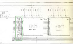
Looking at a Service manual for one of this machine the ram chips are the 2 rows of 9 chips in the bottom left corner of you picture,

ic135 to ic143 being 9 by 256k dram and ic144 to ic152 being the second bank of 9 by 256k dram.
Chips are MN41256-15 (with the 15 means the speed of 150ns) There are other speeds made so if you have to change ram then this is important to note.

Much of the Memory control is handled by a AMS memory Gate array chip IC118 being 40040.
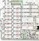
pc1640 MEMORY.jpg

oK So I have highlighted the memory on that clip from the service manual. Look carefully at the pins and solder around them. Also check the green boxed resistors, you may have one of these failed. Use a multimeter on the low ohms range. they are 33ohm value.
pc1640 MEMORY 2.jpg

If you dont find any visible issue, you can possibly try a measuring the heat of each chip with your finger. if one is very hot compared to the others that likely the problem one.

When I have had issues with ram that is soldered in as these appear to be, is rather than try and desolder all, I get a very fine tipped side cutters. ( can let you know model type later) and then with grate care I cut the pins right at side of the ram body. That leaves the legs standing up on the motherboard. Then using a fine tipped temperature controlled soldering iron, and a LOWER melting point fine solder, I solder to the legs a machine tool ic socket. Gold one in preference. Then I can plug in new ram chips.

This is generally easier than trying to desolder the complete chip of out of the motherboard.

In your photo there appears some sort of long 'bracket' maybe between the two rows of 9 ram chips. Not sure as pic is not clear enough. That looks like iif it cannot be removed easily would make soldering piggy back type repair difficult

hope this helps so far
regards
David
 
Not too much to add after the great explanation inotarobot posted above; but apart from a thoroughly cleaning of the area, visual inspection looking for anything unusual (corrosion, metal debris, cracks, etc) you can also try the piggyback testing method. Using a good known 4164 DRAM IC, carefully piggyback it over every IC in the PCB. Power cycle the machine each time and check for changes. With a lot of luck you'll find something.
 
Not too much to add after the great explanation inotarobot posted above; but apart from a thoroughly cleaning of the area, visual inspection looking for anything unusual (corrosion, metal debris, cracks, etc) you can also try the piggyback testing method. Using a good known 4164 DRAM IC, carefully piggyback it over every IC in the PCB. Power cycle the machine each time and check for changes. With a lot of luck you'll find something.

Hi and yes jltursan is right in trying the piggy back method. it has some chance of success locating the faulty ram chip.

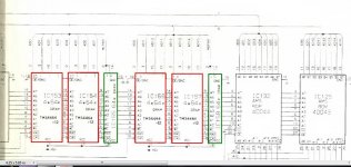
I saw this image in the service manual of this memory circuit chassis memory 4.jpg so check that all 18 memory chips are the the same, it maybe that there are 2 rows of 2 rams (red boxed) , and 1 (green boxed) in each row of a different dram chip as the parity chip. It may be an alternate memory option. If you can work out your board has this specific ram layout then I would try checking, piggybacking or changing IC155 and IC158. However as far as I can see from the photo of your board, your memory is the standard 2 rows of 9 chips.

Just to clarify ""piggyback it over every IC in the PCB"" probably would have been more correctly put as ""piggyback it over every MEMORY IC in the PCB""; but I am sure you would have understood that. Just me been pedantic.
 
Last edited:
I have checked the resistance of the resistors above the memory chips - there are all coming out at 0.33 ohms. I have also checked the temperature of the chips when it is on but they are all cold. Perhaps this is because it has only just got past post before it threw this error. Just to confirm how do I go about piggybacking ICs?
 
There was still a little bit of corrosion on the memory controller - I cleaned this off with vinegar and now I am getting 'Error Faulty real time clock'. Going to try cleaning the battery contacts and putting some batteries in.
 
Cleaned the battery contacts - put new batteries in. Still getting the same error - Checked the voltage going across the wire and see no droppage. Any ideas guys?
 
Got rid of that error...somehow

Now back to square 1. Think I will wait until a bottle of isopropynl alchol arrives then I will give the board a good going over.
 
Hi again,

well the memory controller roms, appear to be in sockets. If you are careful and extract the roms, 1 at a time and with the isopropyl clean the pins, reinsert them. I would not use the liquid on the sockets, on the ic pins. Take real care to put the chip back in the right way round. Do one at a time and try a power cycle to see what if anything changes.

I repeat, do be careful when you plug the rom chips back in, as you would not be the first nor last person to become distracted and plug one in the wrong way round, and destroy the ic on power up.

Piggybacking is best done in my view, by one of 2 means.

1st is by getting a quality machine tool socket then you inset a new ram chip into one. The pins on the machine tool socket are way more rigid, than normal ic sockets, so when you piggy back one of these top of a ram chip the pins should press firmly against the legs of the ram under test.
Rather than bend the machine tool socket short legs out, when I do it i generally just use a tiny bit of downward force and maintain it with a finger, while getting someone else to power machine on.

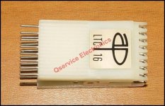
2nd is you get an IC clip like
16pin test clip.jpg

http://www.ebay.com/itm/2-PCS-AP-IC...285539?hash=item21105a7963:g:FtYAAOSw6btXSwoc

and to the pins on top, solder some short flex hook up wire to connect the machine tool socket with the new ram to top of this clip.
Then this way you know you are making a good test connection as you try the piggy back method. Far less chance of shorting something out while manually trying to hold one ic on top another.

This is my PREFERRED method. Obviously more expensive option but if your careful in the soldering of the leads (that will connect to the machine tool socket), to top of clip, then you will leave at least 2 to 3mm of each of the clips top pins clear of solder and wire so as to allow you to clip a oscilloscope probe hook or like to the pin. Thus your still maintaining part of the clips pins as per original.

Sorry for the somewhat long winded wording.

hope that helps.

BTW I would also be checking to see if you have any caps around the memory area. Just occurred to me maybe one of the bypass caps may have gone short, or open. If there are any small tantalum electo caps around this area, check them also.

Actually thinking more about that I suggest you try the following.

1. Disconnect your power supply.
2. with a multimeter on lowest ohms range, connect one lead to a ground power pin (dc zero) then one ram chip at a time, work your way around the pins, try to see if you have a short to zero.
3. repeat the same looking for a short to the +5v.

Also suggest you print out the schematic and do a contunity check on the data and control lines between each ram and the controller chip.

you may just have an open trace under a chip you cannot easily see.
 
Last edited:
one other possibility is you invest in something like a

Bitscope Micro USB Oscilloscope, Logic and Spectrum Analyser, Waveform Generator.

team it up with a Raspberry Pie and use that as your vintage computer test tool.

If I did not already own bench Tektronix Oscilloscopes and Logic analyzers then I would certainly look at buying one for the low cost of Aus$179. In fact if I had enough space cash I buy a few.

from an eBay listing its describe as

This is a fully featured mixed signal test & measurement system, a mixed signal scope in a probe!

20 MHz Bandwidth.
40 MSps Logic Capture.
2 Analog Scope Channels.
2 Analog Comparator channels.
6 Logic/Protocol Analyzer channels.
8 & 12 bit native analog sample resolution.
Decodes Serial, SPI, I2C, CAN and more.
Windows, Linux, Mac OS X & Raspberry Pi.
Built-in analog waveform & clock generators.
User programmable, C/C++, Python, VM API.
Tiny, light weight (14g) and water resistant.

bitscope mixed sig unit.jpg

http://www.ebay.com.au/itm/191862494248?_trksid=p2055119.m1438.l2649&ssPageName=STRK:MEBIDX:IT

there seems a few eBay sellers offering this item
 
Back
Top