• Please review our updated Terms and Rules here

Help me fix my Commodore PET 😀

ARP2600

New Member
Joined
Feb 25, 2024
Messages
5
Hi everyone.

I am trying to fix my trusty little Commodore PET 4016 that was, back in the days, modded to 32K with this RAM arrangement that should be hell to troubleshoot.

I've ordered a ROMULATOR and it boots normally when only dip switch 3 is on, which should be expected, since it replaces RAM and ROM.

I then did a PETTEST on it and god, do I get a lot of errors... I have to assume that the problem is RAM related, but with that much errors, I wonder if it's more of a RAM adressing chip or something?

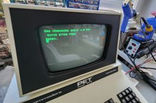
I've then did a PET RAM/ROM/VRAM test and got the faults seen on the associated picture.

What should be my next move? I have a lot of testing equipment, but I'm more into audio devices fixing and low level computing is not where I shine. 🤗

1000011135.jpg1000011183.jpg1000011136.jpg
 
As this is your first post, welcome to VCFED.

Your RAM is always reading $FF (well, at least for pages 0 and 1). So your fears are confirmed, we are going to have to probe the 'stacked' DRAM chips.

It is (however) unlikely to be the DRAM chips (fortunately)... However, we may find the odd one faulty when we get the interface circuitry working.

The first thing to check is the power supplies on the DRAM chips. There should be +5V, +12V and -5V. A voltage rail could have disappeared.

However, first off, can you identify exactly which PCB assembly you have in your PET (Commodore had a habit of stuffing anything that would work into a machine, and/or the machine may have been upgraded/repaired at a later date by a board swap).

On the assumption that I have guessed correctly with regard to the board (!) check for activity on the following pins:

I2 pin 15 (/CAS0).
I2 pin 4 (/RAS0).

[By the way, I mean the ORIGINAL RAM device in I2 - not the stacked one!].

I11 pin 1 (/RAM READ BUFFER ENABLE).
I11 pin 19 (/WRITE).

With my PETTESTER running, you should observe activity on all of these pins.

Dave
 
Last edited:
ASSY 320351.

Omg, you're right. I don't have a 12V rail at the RAM chips.

I can find a 18V (!) going into the cathode side of CR12 and then it goes to mV.

I guess that diode is to be replaced, but before anything, is that 18V means that the 7812 is bad or is it 18V because it has no load?

If that 18V isn't normal and it did once passed through to the ICs, that's a little scary.
 
>>> Omg, you're right. I don't have a 12V rail at the RAM chips.

Rooky mistake - check the power supply rails first :)! Sorry, I couldn't resist...

Forget the diode (CR12) and concentrate on the voltage regulator VR5 (7812).

The 18V is the INPUT side to the +12V regulator. The INPUT voltage needs to be at least 2.5V higher than the OUTPUT voltage it is regulating. So, 12V + 2.5V = 14.5V (minimum). 18V is not out of the question for the INPUT voltage (raw unregulated DC).

The usual fault is that the voltage regulator shuts down if there is a short circuit on the output side feeding the logic.

The most likely cause is a short circuit capacitor - C24, C41, C43 or C83 (according to the schematic diagram) being the most likely (electrolytic - some of which are identified on the Bill of Material as low leakage).

Check with a multimeter (set to resistance with the power to the PET OFF) for a short circuit between the 0V and +12V rails.

Look for a short circuit somewhere with a magnifying glass and bright daylight before doing anything else first.

If there IS a short circuit, you will have to throw a dice as to which component it is... Go for the capacitors first. Remove each one in turn (noting the polarity) and check the capacitor out of the board. If you can, just remove one lead from the board. However, don't get the polarity reversed if it is OK and you re-solder it back in.

Protect the PCB at all costs!

If there is NOT a short circuit indicated, it could be a faulty 7812 voltage regulator.

Dave
 
Last edited:
Oh shit!!! It was C43!!!

You're a pro! Thank you so much. I owe you a beer if you ever travel to Montreal! 🤩
 

Attachments

  • 20240226_154926.jpg
    20240226_154926.jpg
    1.7 MB · Views: 11
Not a bad guess! I like 'easy' faults like that...

I would run the machine with my PETTESTER code to shake out any residual issues with the DRAM. Let it run the DRAM test for about 20 full passes (it takes a while). Make sure at the start of the test it indicates that it has found 32K of DRAM though.

Don't forget to leave me a few 'likes' if I have been helpful...

Dave
 
Pro tip: If you make that trip to Montreal, insist on a trip to Schwartz's.

Heh - that's a flashback, seeing the drilled PCB. At The Computer Shop we used to buy the minimally-populated PETs from Commodore (I honestly can't remember whether it was during times when the max-RAM versions were in short supply or just to increase our margins), then I'd sit down with the iron and solder sucker and populate that second row with DRAM I sourced locally (I had a good relationship with the TI disty and we got a great price on it). Then Commodore started drilling the boards. Then I laid out a board that plugged into sockets that I put down where those buffer chips are. Needed an additional ground wire between the two boards, but other than that it worked perfectly fine and people didn't have to resort to that piggybacked-chips nonsense.
 
Last edited:
Not a bad guess! I like 'easy' faults like that...

I would run the machine with my PETTESTER code to shake out any residual issues with the DRAM. Let it run the DRAM test for about 20 full passes (it takes a while). Make sure at the start of the test it indicates that it has found 32K of DRAM though.

Don't forget to leave me a few 'likes' if I have been helpful...

Dave

20 times later. 🤩

1000011266.jpg
 
Sweet!

There is also a little test program for the IEEE488 interface in an online book entitled "PET and the IEEE 488 Bus (GPIB)" by Eugene Fisher and C.W.Jensen. See Figure 8-1 on page 184.

Type the program in and RUN. No output is good.

 Dave
 
Back
Top