• Please review our updated Terms and Rules here

Battery/CMOS problems with my 286

boggit

Experienced Member
Joined
Jan 4, 2024
Messages
180
Hi all!
  • I recently purchased [this motherboard] from a UK-based seller on eBay. If I've understood everything correctly, [this] is the manual for the motherboard revision in question (3.0). Some specs available on theretroweb.com [here].
  • The seller states the following in the item description:
This motherboard works fine. I have used it myself and given it a good test. When I got the board a few years ago it had sustained some damage from a leaky battery. i thoroughly cleaned the board and repaired 2 traces relating to the keyboard (see pic 3). No other repair was needed. It is now all working as it should.
(My bolding)
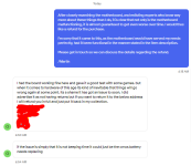
  • Before the purchase, I sent the vendor in question a message, asking if he replaced the leaky battery with a new one. This is the reply I got:
Yes I removed the old clock battery. treated and removed the corrosion. Repaired the broken traces then fitted a brand new battery.
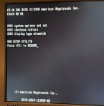
  • When I booted up the system for the first time, I was met with this (as expected):
IMG_8378.jpg
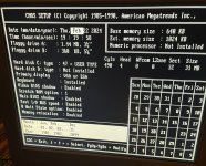
  • I entered all the relevant information and configured the system appropriately. The CMOS setup looks like this (NB: old picture, not reflecting my current hardware outfit, as outlined further down in this post):
IMG_8379.jpg
  • When I set the correct date and time in the CMOS setup, everything seems fine and dandy at first. Both CheckIt Pro and Norton System Information states that CMOS, RTC etc. work correctly...

The problems that I'm experiencing are the following:
  • ...however, I soon noticed that if I, say, turn the computer off at 16:04 and then start it up again at 16:20, the computer thinks that the time of day is still 16:04.
  • Even worse, if I turn the computer off and leave it off for more than an hour or so, I'm once again greeted with worried beeps and the following error messages when I power it up:
CMOS system options not set
CMOS checksum failure
CMOS display type mismatch

RUN SETUP UTILITY
Press <F1> to RESUME
(ie just as in the first image above).
  • Upon entering CMOS Setup, all configurations are back to default values (with 1980, JAN 1 as date, et cetera).

These problems are not of the life-and-death variety, to be sure, but it is rather annoying to have to re-enter all the relevant information into CMOS SETUP again and again.


Additional hardware:

Since I received and installed the motherboard a couple of weeks ago, I've been trying out a variety of ISA cards and such, but below is a list of the current additional hardware that I've outfitted the system with:
  1. An off-brand AT keyboard.
  2. An original IBM CGA card, to which I've connected the EGA monitor mentioned [in this thread].
  3. An I/O card that I cannot seem to find an exact match for when googling around (the card in bottom left of [this picture]), with a game port (to which I have connected a joystick) and an unused parallell port.
  4. A GoldStar Prime 2C I/O/controller card (very close to the one mentioned [here] but of a different make) to which I have connected A) a high density 3½" floppy drive; B) a 360k 5¼" floppy drive; C) [this] IDE-to-CF adapter with a 32 mb. Compact Flash card used as hard drive; D) [this] mouse.

EDIT: Oh, and the motherboard is placed in an IBM 5160/XT case, using the original XT 135W power supply unit to provide juice for the system.
 
Last edited:
It would help if you show us the mainboard so we can see what the seller actually did...

Freezing time when turned off means the RTC chip is not working. Either due to a broken trace or because the new battery has a too-low voltage.

//edit:
Ok, seeing the pictures on ebay: no, that board has not been fixed correctly. There are tons of damaged traces and vias. I would be surprised if the board still works in a few months, as the damage will continue to grow. On the green contacts in the socket left of "C57", you can see that not even vinegar was used to neutralize the leakage.
 
Last edited:
By the looks of it that board suffered a lot of damage from a leaking battery. The trouble is the acid can get between the layers of the board and eat away unseen for a long time causing more damage. Have you checked to see if the board is trying to charge the battery ?
To be honest i wouldn't be happy with it, Get your money back ?
 
It would help if you show us the mainboard so we can see what the seller actually did...

Freezing time when turned off means the RTC chip is not working. Either due to a broken trace or because the new battery has a too-low voltage.

Thank you for responding!

There is a close-up picture of the battery on the eBay link provided above:

s-l1600.jpg


And a more zoomed-out one here:

s-l1600.jpg


I can open the case up and take more pictures after work today, if necessary!
 
By the looks of it that board suffered a lot of damage from a leaking battery. The trouble is the acid can get between the layers of the board and eat away unseen for a long time causing more damage. Have you checked to see if the board is trying to charge the battery ?
Thanks for your reply!

No, I have not done that, and I'm not quite sure how I would go about doing it either. Do I use a multimeter to determine that?
 
Ok, seeing the pictures on ebay: no, that board has not been fixed correctly. There are tons of damaged traces and vias. I would be surprised if the board still works in a few months, as the damage will continue to grow. On the green contacts in the socket left of "C57", you can see that not even vinegar was used to neutralize the leakage.
Oh, that is quite discouraging indeed.

I'll ask for the money back, but the problem is that VAT/import charges/shipping ammounted to over half of the price for the actual motherboard, so still a lot of money thrown into the sea. Oh well.

Thank you for your assessment of my situation, Timo!
 
No, I have not done that, and I'm not quite sure how I would go about doing it either. Do I use a multimeter to determine that?
Yes put your DMM on DC measurement , Measure the battery voltage, Put the black probe on the - side and red on the + side of the battery Do this with the machine turned off and again with the machine running. and note both voltages.
 
Yes put your DMM on DC measurement , Measure the battery voltage, Put the black probe on the - side and red on the + side of the battery Do this with the machine turned off and again with the machine running. and note both voltages.
I haven't gotten around to buying a multimeter yet, but maybe that's something that I should prioritize regardless.

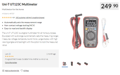
Does this look like something that would do the trick?

multimeter.PNG

(Text in image Google translated from Swedish to English, price equal to around $23-24 US)
 
This board has severe damage and the repair is not exactly nice. I'd just return it because it's not working, and probably more things will fail in the future. In general try to avoid boards that look like this, unless you know exactly what you are getting.
 
I would try to get a refund that allows keeping the board. See, if he returns it, it may get trashed. But the board is repairable - at least at this time. Wait a few months and it's a goner. Most important thing to do would be a bath in white vinegar and then flushing with IPA to stop any further corrosion.
 
I have no experience of UNI-T meters, It looks like a very basic meter but should do the job, You can probably get cheaper than that if you look around.
 
I have contacted the seller and asked for a refund. We'll see what he replies.

A big thanks to all of you for helping me out with this!
 
By the way: Is the situation so dire that I risk causing damage to the ISA cards (and/or the PSU) by having them slotted into this faulty motherboard, or would that be exaggerating it?
 
There's no corrosion visible in any of the ISA slots, so there should be no issue having cards inserted.
 
Back
Top