• Please review our updated Terms and Rules here

5150 Rescue and Repair

Oddsocks

Member
Joined
Mar 3, 2024
Messages
36
I just recently rescued an IBM 5150 complete with keyboard and 5151 monitor from being thrown in the trash, although the 5151 appears to be totally dead but I've done no further diags
  • Early revision 5150 motherboard with all banks populated for a total of 64K
  • "Revision 3" BIOS installed
The first problem was a short on the 12V rail which I guess will surprise no one, was down to a faulty tantalum cap associated with memory bank 1, preventing the power supply from starting. I've replaced this with an electrolytic cap (temporarily) and things progressed further from there. The voltage on the PSU all measure normal when under load from the motherboard. I've configured the system in a "minimum device configuration" setup, however there is no beeps from a known working speaker.

According to (https://www.minuszerodegrees.net/5150/post/5150 - POST - Detailed breakdown.htm) the POST has reached at least step 9, because the timer appears to have been initalised correctly as I see pulses (freq about 66Khz) on pin 9 of the 8253 but I suspect it fails before or at step 19 because I see 118Hz when it's supposed to be outputting 18.2 at this point. So I'm thinking that something is causing a halt from step 10 up to step 19, if that makes sense? I have swapped out the Intel 8088 with an AMD 8088 and the behavious is the same so I'm 99.9% sure there's nothing wrong with the CPU at least and I've confirmed I see 4.77Mhz on the 8284, 8288 and the CPU.

I'm thinking the mostly like fault so far is a RAM fault in bank 0 but I don't have a DRAM tester and I also would like to try one of the diag BIOS ROMs which might help. Is there any advice on which would be the better step next? Also other than the usual suspects getting hot/warm such as the 8088 and the 8284, the resistor at R10 gets very hot. Can anyone confirm is that is normal or if something is drawing more current than it should?
 
Welcome to these forums.

In case you are unaware, there is lots of IBM 5150 information at [here].

The first problem was a short on the 12V rail which I guess will surprise no one, was down to a faulty tantalum cap associated with memory bank 1, preventing the power supply from starting.
For some readers here, it would have been a surprise if you didn't find a short on a 12V rail. :)

According to (https://www.minuszerodegrees.net/5150/post/5150 - POST - Detailed breakdown.htm) the POST has reached at least step 9, because the timer appears to have been initalised correctly as I see pulses (freq about 66Khz) on pin 9 of the 8253 but I suspect it fails before or at step 19 because I see 118Hz when it's supposed to be outputting 18.2 at this point. So I'm thinking that something is causing a halt from step 10 up to step 19, if that makes sense?
It does make sense. And yes, a faulty RAM chip in bank 0 (the soldered-in bank) is a likely cause.

I'm thinking the mostly like fault so far is a RAM fault in bank 0 but I don't have a DRAM tester and I also would like to try one of the diag BIOS ROMs which might help. Is there any advice on which would be the better step next?
I don't know what your soldering skills are like. If they are not good, you could introduce an additional problem. If not good, then I suggest the use of Rudd's Diagnostic ROM as the next step.

although the 5151 appears to be totally dead but I've done no further diags
A known-working 5151 'appears dead' unless it is connected up to a functioning computer (i.e. MDA sync pulses are coming into the 5151).
So for now, assume that the 5151 is good.
Of course, you will know that the 5151 is working if Ruud's Diagnostic ROM displays something.

Also other than the usual suspects getting hot/warm such as the 8088 and the 8284, the resistor at R10 gets very hot. Can anyone confirm is that is normal or if something is drawing more current than it should?
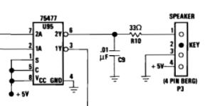
Later, I will bring out one of my known-working 16KB-64KB type of 5150 motherboard, and check out R10.
 
... the resistor at R10 gets very hot. Can anyone confirm is that is normal or if something is drawing more current than it should?
Later, I will bring out one of my known-working 16KB-64KB type of 5150 motherboard, and check out R10.
On my motherboard, R10 is quite warm. Per the section of circuit diagram shown below, R10 is in series with the speaker. At power-on, pin 6 of U95 is driven low (open-collector output), resulting in, on my motherboard, about 3.8 volts over R10. That equates to about 0.44 of a watt, and because of that, R10 is rated at 1/2 watt - the adjacent R6,R7,R8, and R9, are in contrast, rated at 1/4 watt. So, yes, expect R10, when a speaker is connected to the motherboard, to feel quite warm.
1709507810024.png
 
Welcome to these forums.

Thank you, I've been a lurker on and off for a long time but thought I'd actually join,

In case you are unaware, there is lots of IBM 5150 information at [here].

It's been a great source of information and helped immensely thus far.

For some readers here, it would have been a surprise if you didn't find a short on a 12V rail. :)

Ha, very true :)


It does make sense. And yes, a faulty RAM chip in bank 0 (the soldered-in bank) is a likely cause.


I don't know what your soldering skills are like. If they are not good, you could introduce an additional problem. If not good, then I suggest the use of Rudd's Diagnostic ROM as the next step.

Thanks at least I know I'm heading in the right direction. My soldering skills aren't too bad, but I'm never enthusiastic about desoldering ICs on vintage hardware for fear of doing more harm than good so, I think going the diag ROM route makes sense at this point.

Minuszerodegrees suggests that the revision of the BIOS (the 82 rev) I have means that all four banks of RAM must be populated, but it's not clear to me whether the machine would appear dead (ie not POST) or or whether it would just "detect" the wrong amount of RAM if any bank was empty of missing ICs. The reason I ask, is because I was also considering the RAM piggyback method but I'd have to borrow ICs from one of the other banks and of course there's no point in doing that if the banks absolutely must be populated in order to POST successfully.

A known-working 5151 'appears dead' unless it is connected up to a functioning computer (i.e. MDA sync pulses are coming into the 5151).
So for now, assume that the 5151 is good.
Of course, you will know that the 5151 is working if Ruud's Diagnostic ROM displays something.

I did actually read that on Minuszerodegrees but I also assumed that the CRT would appear to "power up", though obviously nothing would display but it sounds like that's not the case so that is good to know.
 
On my motherboard, R10 is quite warm. Per the section of circuit diagram shown below, R10 is in series with the speaker. At power-on, pin 6 of U95 is driven low (open-collector output), resulting in, on my motherboard, about 3.8 volts over R10. That equates to about 0.44 of a watt, and because of that, R10 is rated at 1/2 watt - the adjacent R6,R7,R8, and R9, are in contrast, rated at 1/4 watt. So, yes, expect R10, when a speaker is connected to the motherboard, to feel quite warm.
View attachment 1274812

That is good to know, thank you for confirming. Unexpectedly hot things get my attention, so it's great to be able to rule them out as a problem. :)
 
Welcome to the forum @Oddsocks . I'm jealous. I would love to have an original 5150 with only 64K of RAM. I would enjoy exploring what it was like on that computer right after my NorthStar Horizon and Advantage business computers. My FIL had a 5150 but we upgraded it with a 20MB hard drive and a Hercules card and a full 640K. It ran IBM PC-DOS 3.2 and PFS: Professional Write and R:Base and DacEasy. I ran WordStar on the Advantage at the same time.

Seaken
 
Minuszerodegrees suggests that the revision of the BIOS (the 82 rev) I have means that all four banks of RAM must be populated, but it's not clear to me whether the machine would appear dead (ie not POST) or or whether it would just "detect" the wrong amount of RAM if any bank was empty of missing ICs. The reason I ask, is because I was also considering the RAM piggyback method but I'd have to borrow ICs from one of the other banks and of course there's no point in doing that if the banks absolutely must be populated in order to POST successfully.
At [here], I have, "Note that this 10/27/82 revision BIOS requirement for 4 banks, if not met, does not prevent the motherboard's POST from starting and displaying something on-screen."

I may need to add that information to certain other web pages there.
 
At [here], I have, "Note that this 10/27/82 revision BIOS requirement for 4 banks, if not met, does not prevent the motherboard's POST from starting and displaying something on-screen."

I may need to add that information to certain other web pages there.

Thank you. I managed to rig up a "ROM Adapter" using a breadboard, jump cables and a W27E257 programmed with Ruud's diag rom 4.7.

So when I power on, I hear the relay click and I also hear the short-long-short beeps which if I understand correctly, according to https://www.minuszerodegrees.net/ru... Diagnostic ROM - Breakdown - Version 4.7.htm, we've passed at least step 16. At the moment I have no means of attaching any display to the MDA card (monitor's cable was cut) however when I insert the MDA card in and power on, all I get is a very short high pitched and sometimes low pitched beep and nothing else so I'm not really sure what to make of that. I think my next option is going to have to be seeing if I can get any serial comms happening
 
Thank you. I managed to rig up a "ROM Adapter" using a breadboard, jump cables and a W27E257 programmed with Ruud's diag rom 4.7.

So when I power on, I hear the relay click and I also hear the short-long-short beeps which if I understand correctly, according to https://www.minuszerodegrees.net/ruuds_diagnostic_rom/misc/Ruuds Diagnostic ROM - Breakdown - Version 4.7.htm, we've passed at least step 16. At the moment I have no means of attaching any display to the MDA card (monitor's cable was cut) however when I insert the MDA card in and power on, all I get is a very short high pitched and sometimes low pitched beep and nothing else so I'm not really sure what to make of that. I think my next option is going to have to be seeing if I can get any serial comms happening
I should also add, that I've now tested with the Landmark ROM and I get 5 Hi/Los and 9 short beeps which suggests it cannot initialise the monitor (makes sense, no MDA card etc). However that implies to me it passes all tests up to that point. Hoping my logic is correct there?

Now I know the 16k test isn't supposed to be that reliable with this diag ROM so lets assume it passed "because" :)

If I plug in the MDA card, it immediately fails on the first test, 1 Hi/Lo and actually a long beep I would call it. Ive also been unable to get Ruuds Diag ROM to output anything over serial (tried 2 serial cards) and had the original Memory Expansion installed and presenting memory at A0000.

So I'm left thinking the following
1. The memory is probably bad in bank 0 and the MDA card is also bad
2. The ISA bus isn't functioning correctly for whatever reason
 
Thank you. I managed to rig up a "ROM Adapter" using a breadboard, jump cables and a W27E257 programmed with Ruud's diag rom 4.7.

So when I power on, I hear the relay click and I also hear the short-long-short beeps which if I understand correctly, according to https://www.minuszerodegrees.net/ru... Diagnostic ROM - Breakdown - Version 4.7.htm, we've passed at least step 16. At the moment I have no means of attaching any display to the MDA card (monitor's cable was cut) however when I insert the MDA card in and power on, all I get is a very short high pitched and sometimes low pitched beep and nothing else so I'm not really sure what to make of that.
That sounds very much like an MDA gone faulty in a way that negatively impacts on the ISA bus (i.e. affects address bus, or data bus, etc.)
For example, a chip that is outputting to the data bus (via the ISA slot) at a time when it shouldn't be (either because the chip is faulty, or faulty circuitry on the card is commanding the chip to).
For example, a chip that has gone faulty in a way that heavily/severely loads one of the address or data lines.

I should also add, that I've now tested with the Landmark ROM and I get 5 Hi/Los and 9 short beeps which suggests it cannot initialise the monitor (makes sense, no MDA card etc). However that implies to me it passes all tests up to that point. Hoping my logic is correct there?
The Supersoft/Landmark Diagnostic ROM (SLDR) will be initialising the video card possibly as the very first step. The SLDR manual does not inform us of what it does before it tries to initialise the video card. Certainly, one thing that it must be doing beforehand is to configure the 8255 chip and timer, in order to support beeping of the speaker. Of course, configuring and testing are different things.

This is why the use of Ruud's Diagnostic ROM (RDR) is preferred to the SLDR. RDR is very much documented. Even the source code is available. We know exactly what it gets up to, and when.

I think my next option is going to have to be seeing if I can get any serial comms happening
Ive also been unable to get Ruuds Diag ROM to output anything over serial (tried 2 serial cards) and had the original Memory Expansion installed and presenting memory at A0000.
Note that for at least something to appear on the serial terminal, you don't need a video card nor the IBM memory expansion card. Per the "If you do not ..." section of [here], you would see an initial set of codes, then the 8A code.

- Because the MDA card appears to be 'interfering', that card needs to be out when trying serial comms.
- Maybe the serial cards that you tried are not set to I/O address/port 3F8h. (3F8 is a requirement of RDR.)
- The serial terminal needs to be set to 9600 baud, no parity, 8 data bits, 1 stop bit.
- If you are using a USB-to-RS232 adapter, the particular model could be a problem.

Re that last point. Sometimes, a particular model works in some applications, but not others. For example, the adapter of mine picture at [here] works for RDR and serial drives, but not for transferring the DOS slave program of FastLynx 3.3
 
Re the suspected failure of a RAM chip in bank 0 (the soldered-in bank).

The speaker subsystem is working on your motherboard, and you have the ability to put code into a suitable EPROM/EEPROM.

Therefore, take a look at TEST5099 at [here]. That code (a modified 27OCT82 BIOS) will inform you as two whether the 27OCT82 BIOS is getting as far as the BASE 16K RAM test, and if it is getting that far, signal to you whether the BASE 16K RAM test is passing or failing. If failing, the bit-error-pattern is signaled to you via speaker beeps. Details are within the TEST5099.TXT file within the ZIP download file.
 
Re the IBM MDA card. If we go down the path of the hypothesis that it is interfering with the motherboard address bus or interfering with the motherboard data bus, then I see some means that may fix the problem.

OPTION 1: In turn, replace the chips on the IBM MDA card that are directly connected to the address and data buses. We can inform you of which chips they are.

OPTION 2: In turn, put tape over various contacts on the card's ISA edge connector, in order to work out where the 'interference' is coming from. Then further diagnosis is done from there, informed by the circuit diagram of the IBM MDA card.

OPTION 3: If you have a logic probe (or less preferred, an oscilloscope), use of the procedure at [here]. With the IBM MDA card out, we expect the procedure to pass. With the MDA card out, the procedure may fail, pointing to a particular bit on the address or data bus. Knowing that bit leads to identification of a target chip on the MDA card.

Out of scope of option 1, is the case of faulty MDA circuitry commanding good MDA chips on the address/data bus to output at times when they should not be.
 
The Supersoft/Landmark Diagnostic ROM (SLDR) will be initialising the video card possibly as the very first step. The SLDR manual does not inform us of what it does before it tries to initialise the video card. Certainly, one thing that it must be doing beforehand is to configure the 8255 chip and timer, in order to support beeping of the speaker. Of course, configuring and testing are different things.

Ah, it seems I was under the impression that the beep codes in the table indicated the order in which tests were done, so good go to know. I also just realised your the author of Minuszerodegrees, so thank you very much for such a wealth of information on the subject

Note that for at least something to appear on the serial terminal, you don't need a video card nor the IBM memory expansion card. Per the "If you do not ..." section of [here], you would see an initial set of codes, then the 8A code.

- Because the MDA card appears to be 'interfering', that card needs to be out when trying serial comms.
- Maybe the serial cards that you tried are not set to I/O address/port 3F8h. (3F8 is a requirement of RDR.)
- The serial terminal needs to be set to 9600 baud, no parity, 8 data bits, 1 stop bit.
- If you are using a USB-to-RS232 adapter, the particular model could be a problem.

Re that last point. Sometimes, a particular model works in some applications, but not others. For example, the adapter of mine picture at [here] works for RDR and serial drives, but not for transferring the DOS slave program of FastLynx 3.3

Yeah, I tried both with and without the MDA card. Serial config was set 9600 8N1 and I tried with the original serial card (which I believe would be on 3F8) as well as another Multi/IO card and confirmed COM 1 was on 3F8. I was using a USB to RS232 but I can eliminate that as a causing by using and older PC with a built in serial port.
 
Re the suspected failure of a RAM chip in bank 0 (the soldered-in bank).

The speaker subsystem is working on your motherboard, and you have the ability to put code into a suitable EPROM/EEPROM.

Therefore, take a look at TEST5099 at [here]. That code (a modified 27OCT82 BIOS) will inform you as two whether the 27OCT82 BIOS is getting as far as the BASE 16K RAM test, and if it is getting that far, signal to you whether the BASE 16K RAM test is passing or failing. If failing, the bit-error-pattern is signaled to you via speaker beeps. Details are within the TEST5099.TXT file within the ZIP download file.

When using TEST5099 ROM I simply get a long continuous tone from the speaker and nothing else. This is same behaviour I get when starting the 5150 without an ROM in the socket. I did do sanity checks by rinsing and repeating a few times to confirm there was no issue with the ROM itself. Given the issue with the MDA card and the unexpected behaviour with this ROM, is it reasonble to think there could be a problem with the data or address lines? In such a way that some ROMs execute to a certain point, before corruption occurs? I did also notice that you have other TEST ROMS which could potentially help with this, however at this point I don't own a logic probe or analyser - only an oscilloscope.

Even though I've checked the wiring 3 times and it all looks correct ()https://forum.vcfed.org/index.php?threads/27256-adapter-for-ibm-5150.13478), I'm not trusting this breadboard ROM adapter I knocked up so I think I just need to bite the bullet and order one before I go down a rabbit hole.
 
Last edited:
Yeah, I tried both with and without the MDA card. Serial config was set 9600 8N1 and I tried with the original serial card (which I believe would be on 3F8) as well as another Multi/IO card and confirmed COM 1 was on 3F8. I was using a USB to RS232 but I can eliminate that as a causing by using and older PC with a built in serial port.
Incorrect cable ?

You have an oscilloscope. You could hook it up to the 'transmit data' pin on the 5150's serial port and see if data is being sent.
 
Even though I've checked the wiring 3 times and it all looks correct ()https://forum.vcfed.org/index.php?threads/27256-adapter-for-ibm-5150.13478), I'm not trusting this breadboard ROM adapter I knocked up so I think I just need to bite the bullet and order one before I go down a rabbit hole.
You are hearing the relay click and the short-long-short beeps, both produced by RDR, and so most of the pins on your adapter must be hooked up okay. The data pins will be good. If anything is astray, it would be the upper address lines.
 
You are hearing the relay click and the short-long-short beeps, both produced by RDR, and so most of the pins on your adapter must be hooked up okay. The data pins will be good. If anything is astray, it would be the upper address lines.

That is true, but I also noticed that the original ROM imaged programmed into the EEPROM behaved the same way as the TEST5099 ROM image (ie long continuous beep), yet placing the original ROM IC back in the socket and it behaved as "normal" as it did before, so I'm not really trusting the breadboard setup I did at this point. I've dragged out the 486 and I'm going to sanity check the serial cards, serial cables etc to make sure they really do work. I'm also thinking that at least in theory, I could check out the MDA card and ST505 card on the 486 as the BIOS states Mono as an option.
 
Well plugged the MDA into the 486, configured the BIOS to Mono, connected up the 5151 and the whole thing came to life - so that's fantastic - the MDA and the 5151 are working, after the cable repair. :) I've also tried the DTC5150 (Rev 2) controller in the 486 and while it will say "1 HardDisk" presumably from it's BIOS, I can't actually get it to boot (even without the IDE controller in it), it just says "PRESS A KEY TO REBOOT" - but whether that is coming from the MBR or the BIOS, I'm not sure yet but it seems to work at least superficially
 
Last edited:
Well plugged the MDA into the 486, configured the BIOS to Mono, connected up the 5151 and the whole thing came to life - so that's fantastic - the MDA and the 5151 are working, after the cable repair. :)
I can see why you are pleased with that.

So, what's going on with "however when I insert the MDA card in and power on, all I get is a very short high pitched and sometimes low pitched beep and nothing else so I'm not really sure what to make of that."
To me, it is now sounding like a situation of 'multiple variables were changed, and a resulting symptom attributed to the wrong changed variable'.

That is true, but I also noticed that the original ROM imaged programmed into the EEPROM behaved the same way as the TEST5099 ROM image (ie long continuous beep), yet placing the original ROM IC back in the socket and it behaved as "normal" as it did before, so I'm not really trusting the breadboard setup I did at this point.
Agreed. Re the continuous beep. See my hypothesis at [here]. It sounds like you have one of the subject motherboards - with no U33, or a compromised U33, a continuous (or intermittent) tone is heard.
 
I've also tried the DTC5150 (Rev 2) controller in the 486 and while it will say "1 HardDisk" presumably from it's BIOS, I can't actually get it to boot (even without the IDE controller in it), it just says "PRESS A KEY TO REBOOT" - but whether that is coming from the MBR or the BIOS, I'm not sure yet but it seems to work at least superficially
The BIOS chip on the DTC5150, a card designed for PC's and XT's, will not be inspecting the AT's CMOS configuration settings. I think it likely that the DTC5150's BIOS chip is discovering that on its control cable, there is a drive at 0 reporting as 'ready, and no drive at 1 reporting as ready, i.e. one drive is attached, and the BIOS consequently displays "1 HardDisk". If you disconnect the control cable, you may see "1701" instead (the DTC5150 expecting at least one drive connected to it).

The DTC5150 manuals do not indicate AT compatibility. There may be stability issues when the card is in an AT-class machine.
 
Back
Top