n0p
Experienced Member
Ever since getting Book V1 i though of connecting external keyboard to it, as original one is barely usable.
First point was to understand how keyboard is implemented in the Book.
As @Retroplayer and @sergey found out, keyboard chip, marked "BK82C42" is actually an STC micro microcontroller STC8G.


it sets keyboard scancode on XT-IO CPLD chip, lines marked KD0-KD7 and pulses interrupt to 8259.

To understand more, i connected Pi Pico to those lines, but as Pico is not 5V tolerant, voltage should be reduced first, and it would be nice to understand will 3.3V work for STC8G, CPLD chip and interrupt controller.
It actually did") I've cut 5V line from STC8G and supplied 3.3V to it and everything worked fine: https://forum.vcfed.org/index.php?t...dification-thread.1245155/page-5#post-1347572
I've cut 5V line from STC8G and supplied 3.3V to it and everything worked fine: https://forum.vcfed.org/index.php?t...dification-thread.1245155/page-5#post-1347572
Values were: Interrupt line is high on event for ~6130us, first repeat delay ~620'000us, next repeat delay ~61'550us. So some main cycle on microcontroller is 6ms.
Second point - how do i use that?
The idea was to disconnect keyboard chip from XT-IO and put small Pico in between, as it has just enough lines for it, supports USB HID devices via TinyUSB lib, so Pico would read both our keyboards, set lines on XT-IO chip and signal interrupt.
Smallest Pico clone i found locally is Waveshare Zero, which is really small, but instead of nice simple green indicator led of original Pico it has some RGB thing i couldn't light But it has a Type-C USB which is always a plus.
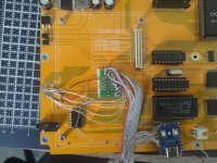
Next, i needed to solder to board lines and that was the hardest part of the whole project. I managed to find some PTFE AWG36 wire here and that helped a lot. Then used a dip2soic small adapter board to solder thicker wires to connect Pico output (to XT-IO) lines to add some sturdiness to that contraption


Position of Waveshare Zero was chosen to allow access to it's boot button, so firmware could be updated in assembled Book, but...
When connecting input lines from keyboard microcontroller i did something wrong and chip died.
I asked seller to send me it and he agreed, though at first he sent LCD board instead i didn't ask for (some kind of general protocol? "I don't understand what he wants, send him an LCD board!"), but second time he sent even two keyboard chips
While waiting for chips i slowly worked on firmware for Pico, it worked pretty much fine.
Even Shamus worked quite nice, not running into walls if key held too long. I did notice a bit strange behavior (key not registered, but very rare occurrence) of LodeRunner but at that time somewhat ignored that.
When i finally recieved keybaord chips i did one thing i overlooked from start - we can supply 3.3V to STC8G right from Pico, w/o Zener diode. Pico itself is powered from Book 5V line.
Time to assembly the Book back:


All good As a bonus, i can now power Book with USB Type C cable
Last part, the technical debt
I actually noticed the problem with LodeRunner becomes worse when i used my old 8088 clone chip with DMA memory refresh enabled. Sometimes key just was not registered and for dynamic game it's just unacceptable.
More, it uses int 16h and that the nicest way, what could the problem be there? Key input worked better with disabled sound. I suggested 6ms is not enough time for key to be registered at this computing speed. I do understand that it's IRQ-driven, but there's no acknowledge line back from XT-IO. More, i tested LodeRunner on my V2 and it did behave the same way unmodded (so far) - you can get first right-bottom chest w/o digging, and if you press left after getting it key will not be registered at about 30% success rate. I tried increasing keyboard "cycle", and at somewhat 30ms cycle time it got better. So i did normal FIFO buffer this time and split processing into three logical parts: get and push key to buffer several times, if key in buffer, set lines and raise interrupt, get and push keys again and lower interrupt. At 40ms full cycle game worked just right at XT exact original speed, hooray! I did test a lot of other games and so far didn't notice problems in input.

Source for firmware: https://github.com/jinshin/BookKbd/blob/stable/book_kbd.c
First point was to understand how keyboard is implemented in the Book.
As @Retroplayer and @sergey found out, keyboard chip, marked "BK82C42" is actually an STC micro microcontroller STC8G.
it sets keyboard scancode on XT-IO CPLD chip, lines marked KD0-KD7 and pulses interrupt to 8259.
To understand more, i connected Pi Pico to those lines, but as Pico is not 5V tolerant, voltage should be reduced first, and it would be nice to understand will 3.3V work for STC8G, CPLD chip and interrupt controller.
It actually did
I've cut 5V line from STC8G and supplied 3.3V to it and everything worked fine: https://forum.vcfed.org/index.php?t...dification-thread.1245155/page-5#post-1347572Values were: Interrupt line is high on event for ~6130us, first repeat delay ~620'000us, next repeat delay ~61'550us. So some main cycle on microcontroller is 6ms.
Second point - how do i use that?
The idea was to disconnect keyboard chip from XT-IO and put small Pico in between, as it has just enough lines for it, supports USB HID devices via TinyUSB lib, so Pico would read both our keyboards, set lines on XT-IO chip and signal interrupt.
Smallest Pico clone i found locally is Waveshare Zero, which is really small, but instead of nice simple green indicator led of original Pico it has some RGB thing i couldn't light
But it has a Type-C USB which is always a plus.Next, i needed to solder to board lines and that was the hardest part of the whole project. I managed to find some PTFE AWG36 wire here and that helped a lot. Then used a dip2soic small adapter board to solder thicker wires to connect Pico output (to XT-IO) lines to add some sturdiness to that contraption
Position of Waveshare Zero was chosen to allow access to it's boot button, so firmware could be updated in assembled Book, but...
When connecting input lines from keyboard microcontroller i did something wrong and chip died.
I asked seller to send me it and he agreed, though at first he sent LCD board instead i didn't ask for (some kind of general protocol? "I don't understand what he wants, send him an LCD board!"), but second time he sent even two keyboard chips
While waiting for chips i slowly worked on firmware for Pico, it worked pretty much fine.
Even Shamus worked quite nice, not running into walls if key held too long. I did notice a bit strange behavior (key not registered, but very rare occurrence) of LodeRunner but at that time somewhat ignored that.
When i finally recieved keybaord chips i did one thing i overlooked from start - we can supply 3.3V to STC8G right from Pico, w/o Zener diode. Pico itself is powered from Book 5V line.
Time to assembly the Book back:
All good
As a bonus, i can now power Book with USB Type C cable Last part, the technical debt
I actually noticed the problem with LodeRunner becomes worse when i used my old 8088 clone chip with DMA memory refresh enabled. Sometimes key just was not registered and for dynamic game it's just unacceptable.
More, it uses int 16h and that the nicest way, what could the problem be there? Key input worked better with disabled sound. I suggested 6ms is not enough time for key to be registered at this computing speed. I do understand that it's IRQ-driven, but there's no acknowledge line back from XT-IO. More, i tested LodeRunner on my V2 and it did behave the same way unmodded (so far
) - you can get first right-bottom chest w/o digging, and if you press left after getting it key will not be registered at about 30% success rate. I tried increasing keyboard "cycle", and at somewhat 30ms cycle time it got better. So i did normal FIFO buffer this time and split processing into three logical parts: get and push key to buffer several times, if key in buffer, set lines and raise interrupt, get and push keys again and lower interrupt. At 40ms full cycle game worked just right at XT exact original speed, hooray! I did test a lot of other games and so far didn't notice problems in input.Source for firmware: https://github.com/jinshin/BookKbd/blob/stable/book_kbd.c