gfmoore
Member
I am very confused. If I have a single floppy drive in my machine then are the following correct?
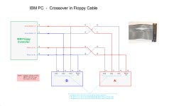
The ribbon cable connector that plugs into the drive is after the twist.
The drive has the resistor array plugged in to terminate it as it is currently furthest away from the controller.
Since the drive is DS0 it should be jumpered between pins 2 and 15 That is the second row?
Now this won't work, but if I jumper the pins between the third row 3 and 14 DS1 then at least the motor spins and the drive light comes on -not able to read any of my disks, probably formatted wrong.
If I were to have two drives then the second "B:" drive goes before the twist and it does not have the termination and the jumper should then be the third row? i.e. DS1 for the second drive and the A drive at the end of the cable is DS0, the second row?.
It's the jumpering that has me confused.

In this diagram I am assuming that in the two drive model the first drive is B and the second drive is A
The ribbon cable connector that plugs into the drive is after the twist.
The drive has the resistor array plugged in to terminate it as it is currently furthest away from the controller.
Since the drive is DS0 it should be jumpered between pins 2 and 15 That is the second row?
Now this won't work, but if I jumper the pins between the third row 3 and 14 DS1 then at least the motor spins and the drive light comes on -not able to read any of my disks, probably formatted wrong.
If I were to have two drives then the second "B:" drive goes before the twist and it does not have the termination and the jumper should then be the third row? i.e. DS1 for the second drive and the A drive at the end of the cable is DS0, the second row?.
It's the jumpering that has me confused.
In this diagram I am assuming that in the two drive model the first drive is B and the second drive is A
")